
Corvette V8-6.2L (2008)
Engine Control Module: Service and Repair
Engine Control Module Replacement
Engine control module (ECM) service should normally consist of either ECM replacement or electrically erasable programmable read only memory
(EEPROM) programming. If the diagnostic procedures require ECM replacement, check the ECM first to see if the correct part is being used.
Important: In order to prevent internal ECM damage, the ignition must be OFF when you disconnect or reconnect the power to the ECM. For
example, disconnect the power when you work with the following components:
*
A battery cable
*
The ECM pigtail
*
The ECM fuse
*
The jumper cables
Important:
*
When you diagnose or replace the ECM, remove any debris from the ECM connector surfaces before servicing the ECM module
connector gaskets. Ensure that the gaskets are installed correctly. The gaskets prevent intrusion into the ECM.
*
The replacement ECM MUST be programmed.
Removal Procedure
Important: It is necessary to record the remaining engine oil life. If the replacement module is not programed with the remaining engine oil
life, the engine oil life will default to 100 percent. If the replacement module is not programmed with the remaining engine oil life, the engine oil
will need to be changed at 5 000 km (3,000 mi) from the last engine oil change.
1. Using a scan tool, retrieve the percentage of remaining engine oil. Record the remaining engine oil life.
2. Remove the wheelhouse filler panel. Refer to Front Wheelhouse Liner Replacement (Rear Liner) (See: Body and Frame/Fender/Front
Fender/Front Fender Liner/Service and Repair)Front Wheelhouse Liner Replacement (Front Liner) (See: Body and Frame/Fender/Front
Fender/Front Fender Liner/Service and Repair) .
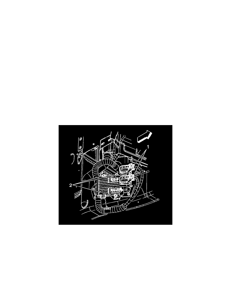
3. Disconnect the engine wiring harness electrical connectors (1) from the ECM.
4. Remove the ECM bolts (2).
5. Remove the ECM.
Installation Procedure