
Corvette V8-6.2L (2008)
Front Steering Knuckle: Service and Repair
Front Suspension
Steering Knuckle Replacement
Tools Required
J 42188 Ball Joint Separator
Removal Procedure
1. Raise and support the vehicle. Refer to Lifting and Jacking the Vehicle (See: Maintenance/Service Intervals) .
2. Remove the brake caliper and rotor. Refer to Front Brake Rotor Replacement (See: Brakes and Traction Control/Disc Brake System/Brake
Rotor/Disc/Service and Repair/Removal and Replacement/Front Brake Rotor Replacement) and Front Brake Caliper Replacement (J56) (See:
Brakes and Traction Control/Disc Brake System/Brake Caliper/Service and Repair/Removal and Replacement/Front Brake Caliper Replacement
(J56))Front Brake Caliper Replacement (JL9-J55) (See: Brakes and Traction Control/Disc Brake System/Brake Caliper/Service and
Repair/Removal and Replacement/Front Brake Caliper Replacement (JL9-J55)) .
3. Remove the stabilizer shaft link from the lower control arm.
4. Disconnect the wheel speed sensor electrical connector.
5. Support the lower control arm using a jackstand.
6. Separate the steering linkage outer tie rod ball stud from the steering knuckle using J 42188 . Refer to Rack and Pinion Outer Tie Rod End
Replacement (See: Tie Rod/Tie Rod End/Service and Repair) .
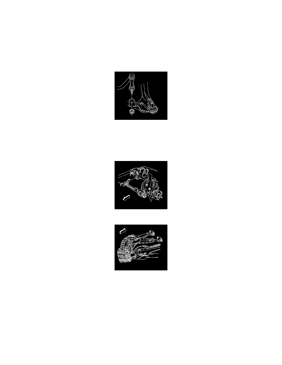
7. Separate and remove the upper control arm ball joint stud from the steering knuckle using J 42188 . Refer to Upper Control Arm Replacement (
See: Suspension/Control Arm/Service and Repair/Front Suspension/Upper Control Arm Replacement) .
8. Using J 42188 separate and remove the lower ball joint stud from the steering knuckle. Refer to Lower Control Arm Replacement (See:
Suspension/Control Arm/Service and Repair/Front Suspension/Lower Control Arm Replacement) .
9. Remove the steering knuckle from the vehicle.
Installation Procedure