
Corvette V8-6.2L (2008)
Steering Gear: Service and Repair
Steering Gear Replacement
Steering Gear Replacement
Tools Required
J 33432-A Leaf Spring Compressor
Removal Procedure
1. Raise and support the vehicle. Refer to Lifting and Jacking the Vehicle (See: Maintenance/Service Intervals) .
2. Remove the tires and wheels. Refer to Tire and Wheel Removal and Installation (See: Wheels and Tires/Service and Repair) .
3. Disconnect the tie rod ends from the steering knuckles. Refer to Rack and Pinion Outer Tie Rod End Replacement (See: Tie Rod/Tie Rod
End/Service and Repair) .
4. Disconnect the intermediate shaft from the power steering gear. Refer to Intermediate Steering Shaft Replacement (See: Steering Column/Service
and Repair/Intermediate Steering Shaft Replacement) .
5. Remove the stabilizer shaft. Refer to Stabilizer Shaft Replacement (See: Suspension/Stabilizer Bar/Service and Repair/Front Suspension) .
6. Remove the power steering pressure and return hoses from the power steering gear.
7. Remove the power steering line hold-downs from the crossmember.
8. Remove the brake pressure modulator valve (BPMV) bracket. Refer to Brake Pressure Modulator Valve Bracket Replacement (See: Brakes and
Traction Control/Antilock Brakes / Traction Control Systems/Hydraulic Control Assembly - Antilock Brakes/Service and Repair/Brake Pressure
Modulator Valve Bracket Replacement) .
9. Remove the 2 front crossmember mounting nuts.
10. Using hand tools only, LOOSEN, Do Not Remove, the 2 rear crossmember mounting nuts 10 mm (0.394 in).
11. Disconnect the height sensor arm to the control arm.
12. Use a utility stand to support the front of the crossmember.
13. Using the J 33432-A , by compressing the coil spring, it will allow the crossmember to lower enough to properly remove the gear.
14. Remove the lower shock mounting bolts.
15. Remove the brake pipe bracket for the left front brake caliper from the crossmember.
16. Remove the plastic brake pipe hold-down for the right front brake pipe.
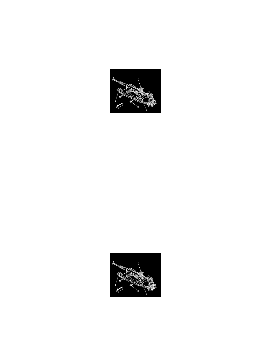
17. Remove the power steering gear mounting bolts (3) and nuts (2).
18. Maneuver the power steering gear around the brake lines (1) from the vehicle through the left wheelhouse opening.
Installation Procedure
Important: For Z06 applications, replace the crossmember-to-steering gear insulators.
1. Install the power steering gear (1) into the vehicle through the left wheelhouse opening.
Notice: Refer to Fastener Notice (See: Service Precautions/Vehicle Damage Warnings/Fastener Notice) .
2. Install the power steering gear mounting bolts (3) and nuts (2).
Tighten the nuts to 100 N.m (74 lb ft).