
Corvette V8-6.2L (2008)
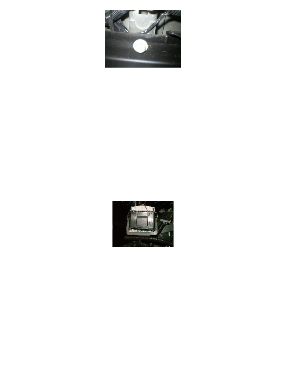
5. Inspect the wiring harness near the data link resistor, between the truck box and frame for chafed/shorted wiring as shown. Refer to Wiring
Systems and Power Management > Component Locator > Master Electrical Component List > Data Link Resistor in SI.
If the wiring is damaged, repair as needed. Refer to Wiring Systems and Power Management > Diagnostic Information and Procedures > Wiring
Repairs in SI.
6. Disconnect the electrical connector from the data link resistor.
7. Test the resistor for 110-130ohm.
‹› If not within the specified range, replace the data link resistor.
‹› If within the specified range, refer to Scan Tool Does Not Communicate with High Speed GMLAN Device in SI.
8. Connect the electrical connector to the data link resistor. Secure the resistor as needed.
9. Protect the harness by covering the sharp edge with butyl tape or a suitable material. Secure the harness as needed.
10. Lower the vehicle.
11. Connect the negative battery cable. Refer to Battery Negative Cable Disconnection and Connection in SI.
12. Clear any DTCs that may be present with a scan tool and verify the proper operation of the vehicle.
Inspection of Engine Harness
Inspection of Engine Harness Connector X109 for Backed Out or Bent Terminals and Poor Connections
1. Turn OFF the ignition and all accessories.
2. Disconnect the negative battery cable. Refer to Battery Negative Cable Disconnection and Connection in SI.
3. Locate the X109 connector. Refer to Wiring Systems and Power Management > Component Locator > Master Electrical Component List > X109
in SI.
4. Before disconnecting, verify the connector is fully seated together even though the lever is locked down as shown.
If the connector is not fully seated, repair as needed. Refer to Wiring Systems and Power Management > Diagnostic Information and Procedures >
Connector Repairs in SI.
5. Inspect the connector for the following conditions:
-
Backed out terminals
-
Bent pins
-
Corrosion
-
Poor terminal fit (use the correct test probe)
‹› If a condition is found, repair as needed. Refer to Wiring Systems and Power Management > Diagnostic Information and Procedures in SI.
AND
‹› If corrosion is found, proceed to the section of the bulletin titled: Repairing Fretting Corrosion to complete the repair.
6. Connect the negative battery cable. Refer to Battery Negative Cable Disconnection and Connection in SI.
7. Clear any DTCs that may be present with a scan tool and verify the proper operation of the vehicle.
Inspection of Engine Harness Connector X115 for Backed Out or Bent Terminals and Poor Connections
1. Turn OFF the ignition and all accessories.