
Corvette V8-6.2L (2008)
2. Disconnect the negative battery cable. Refer to Battery Negative Cable Disconnection and Connection in SI.
3. Locate the X115 connector. Refer to Wiring Systems and Power Management > Component Locator > Master Electrical Component List > X115
in SI.
4. Inspect the connector for the following conditions:
-
Backed out terminals
-
Bent pins
-
Corrosion
-
Poor terminal fit (use the correct test probe)
‹› If a condition is found, repair as needed. Refer to Wiring Systems and Power Management > Diagnostic Information and Procedures in SI.
AND
‹› If corrosion is found, proceed to the section of the bulletin titled: Repairing Fretting Corrosion to complete the repair.
5. Connect the negative battery cable. Refer to Battery Negative Cable Disconnection and Connection in SI.
6. Clear any DTCs that may be present with a scan tool and verify the proper operation of the vehicle.
Hybrid Models Chafed Wiring Harness Locations/Inspections
Hybrid Models (HP2) Chafed Wiring Harness Locations and Inspection of Engine Harness Connector X150 for Backed Out Terminals and
Poor Connections at Ground Locations G102 and G300
1. Turn OFF the ignition and all accessories.
2. Disconnect the negative battery cable. Refer to Battery Negative Cable Disconnection and Connection in SI.
3. Locate the X150 connector. Refer to Wiring Systems and Power Management > Component Locator > Master Electrical Component List > X150
in SI.
4. Inspect the connector for the following conditions:
-
Backed out terminals
-
Bent pins
-
Corrosion
-
Poor terminal fit (use the correct test probe)
‹› If a condition is found, repair as needed. Refer to Wiring Systems and Power Management > Diagnostic Information and Procedures in SI.
AND
‹› If corrosion is found, proceed to the section of the bulletin titled: Repairing Fretting Corrosion to complete the connector repair.
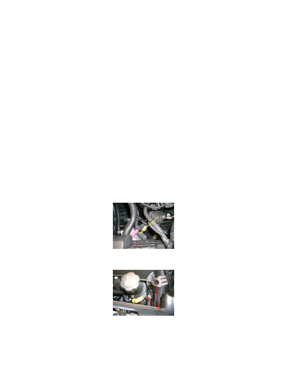
5. Inspect for a misrouted/chafed harness rubbing on the cooling fins of the Transmission Auxiliary Fluid Pump Control Module as shown.
If the wiring is damaged, repair as needed. Refer to Wiring Systems and Power Management > Diagnostic Information and Procedures in SI.
6. Inspect for a chafed harness caused by a mispositioned retaining clip as shown. The chafing condition usually occurs when the tab of the clip is
aligned with a slot in the conduit.
If the wiring is damaged, repair as needed. Refer to Wiring Systems and Power Management > Diagnostic Information and Procedures in SI.
7. Locate ground connections G102 and G300. Refer to Wiring Systems and Power Management > Component Locator > Master Electrical
Component List > G102 and G300 in SI.
8. Inspect G102 and G300 for a clean and tight connection. Undercoating has been found between the eyelet and the frame resulting in a poor
connection.