
Corvette V8-6.2L (2008)
Heated Glass Element: Testing and Inspection
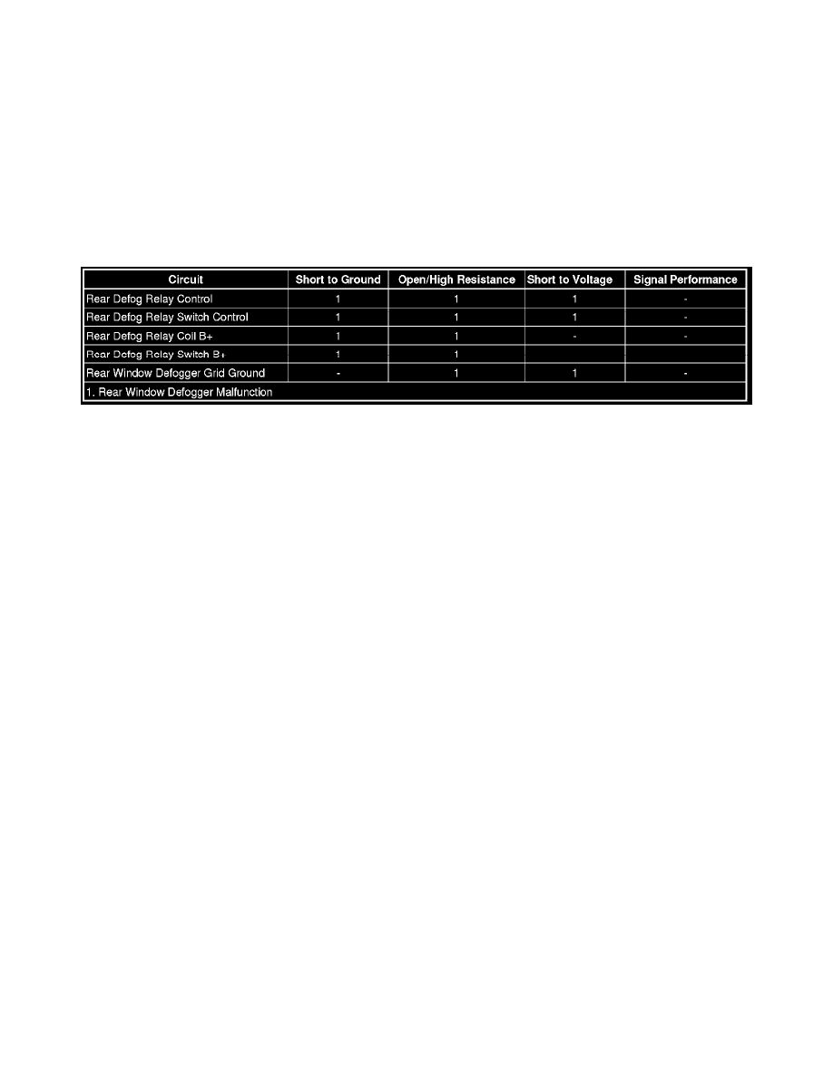
Rear Window Defogger Malfunction
Diagnostic Instructions
*
Perform the Diagnostic System Check - Vehicle (See: Testing and Inspection/Initial Inspection and Diagnostic Overview/Diagnostic System
Check - Vehicle) prior to using this diagnostic procedure.
*
Review Strategy Based Diagnosis (See: Testing and Inspection/Initial Inspection and Diagnostic Overview/Strategy Based Diagnosis) for an
overview of the diagnostic approach.
*
Diagnostic Procedure Instructions (See: Testing and Inspection/Initial Inspection and Diagnostic Overview/Diagnostic Procedure Instructions)
provides an overview of each diagnostic category.
Diagnostic Fault Information
Circuit/System Description
When the rear window defogger switch is activated, the HVAC control module energizes the rear defog relay by grounding the rear defog relay control
circuit. When the rear defog relay coil is energized, the switch contacts of the rear defog relay close allowing battery voltage to flow from the BATT 2
fuse through the closed switch contacts and out the relay switched output to the rear window defogger grid. Ground for the rear window defogger grid is
provided at G301.
Reference Information
Schematic Reference
Defogger Schematics (See: Diagrams/Electrical Diagrams)
Connector End View Reference
Component Connector End Views (See: Diagrams/Connector Views)
Description and Operation
Rear Window Defogger Description and Operation (See: Windows/Description and Operation/Rear Window Defogger Description and Operation)
Electrical Information Reference
*
Circuit Testing (See: Testing and Inspection/Component Tests and General Diagnostics)
*
Connector Repairs (See: Testing and Inspection/Component Tests and General Diagnostics)
*
Testing for Intermittent Conditions and Poor Connections (See: Testing and Inspection/Component Tests and General Diagnostics)
*
Wiring Repairs (See: Testing and Inspection/Component Tests and General Diagnostics)
Scan Tool Reference
Control Module References (See: Testing and Inspection/Programming and Relearning)
Circuit/System Testing
1. Ignition OFF, disconnect the rear window defog relay.
2. Ignition ON, verify that a test lamp does not illuminate between the control circuit terminal C19 and ground.
‹› If the test lamp illuminates, test the control circuit for a short to voltage.
3. Verify that a test lamp illuminates between the relay coil B+ circuit terminal A19 and ground.
‹› If the test lamp does not illuminate, test the relay coil B+ circuit for a short to ground or an open/high resistance.
4. Verify that a test lamp illuminates between the relay switch B+ circuit terminal A18 and ground.