
Corvette V8-7.0L (2007)
Data Link Connector: Testing and Inspection
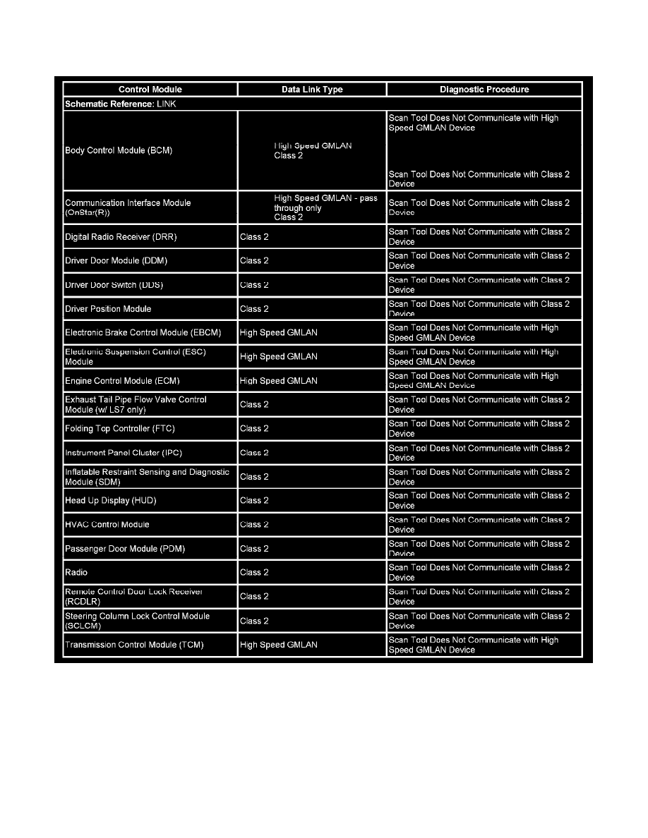
Data Link References
This table identifies which serial data link that a particular module uses for in-vehicle data transmission. Some modules may use more than one data link
to communicate. Some modules may have multiple communication circuits passing through them without actively communicating on that data link. This
table is used to assist in correcting a communication malfunction. The BCM emulates some devices that are on high speed GMLAN serial data circuit to
the modules on class 2 serial data circuit. The BCM transmits multiple Node Alive messages using source IDs that correspond to each of those high
speed GMLAN nodes. This is in addition to the BCM behaving itself as a real node. For the description and operation of these serial data communication
circuits refer to Data Link Communications Description and Operation.
Important: If the scan tool does not communicate with the vehicle the class two serial data bus must be diagnosed, repaired and functional first
in order to prevent misdiagnosis.