
Cruze L4-1.4L Turbo (2011)
Brake Rotor/Disc: Testing and Inspection
Brake Rotor Assembled Lateral Runout Correction - Indexing
Brake Rotor Assembled Lateral Runout Correction - Indexing
Special Tools
CH 45101-100 - Conical Brake Rotor Washers
For equivalent regional tools, refer to Special Tools (See: Tools and Equipment).
Warning: Refer to Brake Dust Warning (See: Service Precautions/Technician Safety Information/Brake Dust Warning).
Note:
*
Brake rotor thickness variation MUST be checked BEFORE checking for assembled lateral runout (LRO). Thickness variation exceeding the
maximum acceptable level can cause brake pulsation. Refer to Brake Rotor Thickness Measurement (See: Brake Rotor Thickness Measurement).
*
Brake rotor assembled LRO exceeding the maximum allowable specification can cause thickness variation to develop in the brake rotor over time,
usually between 4 800 - 11 300 km (3,000 - 7,000 mi). Refer to Brake Rotor Assembled Lateral Runout Measurement (See: Brake Rotor
Assembled Lateral Runout Measurement).
1. Remove the CH 45101-100 - washers and the lug nuts that were installed during the assembled LRO measurement procedure.
2. Inspect the mating surface of the hub/axle flange and the brake rotor to ensure that there are no foreign particles or debris remaining.
3. Index the brake rotor in a different orientation to the hub/axle flange.
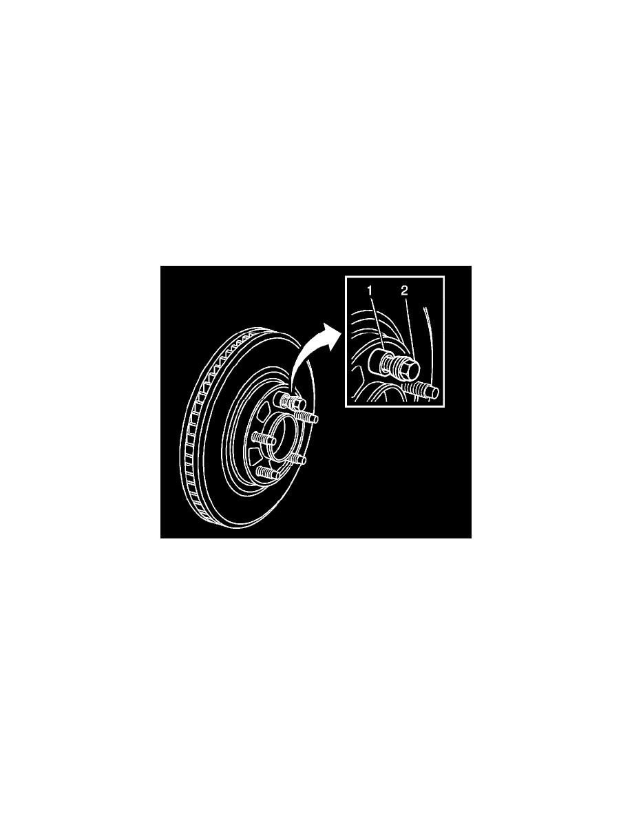
4. Hold the rotor firmly in place against the hub/axle flange and install one of the CH 45101-100 - washers (1) and one lug nut (2) onto the
upper-most wheel stud.
5. Continue to hold the rotor secure and tighten the lug nut firmly by hand.