
Cruze L4-1.4L Turbo (2011)
Ignition Switch Lock Cylinder: Service and Repair
Key and Lock Cylinder Coding
Ignition Lock Cylinder
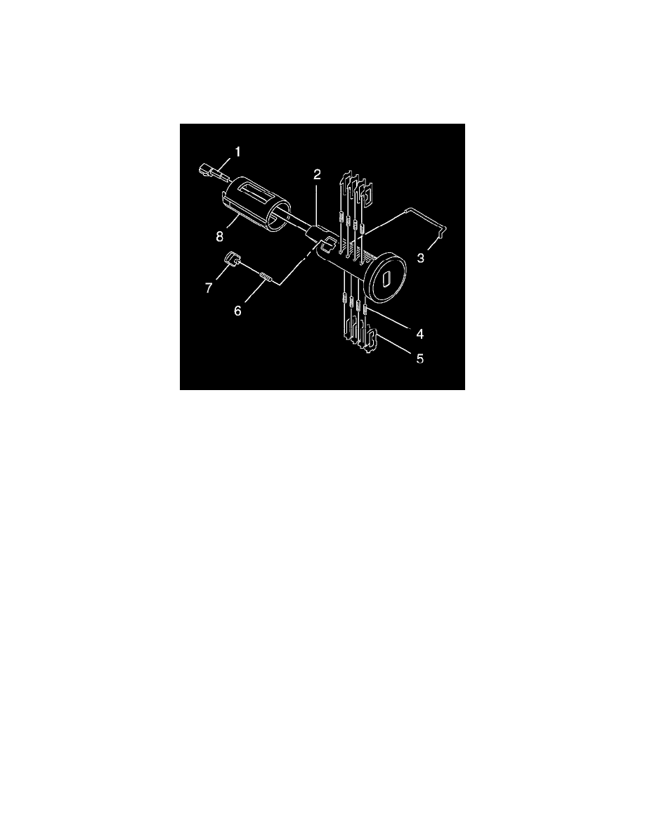
The ignition lock cylinder uses 8 key cut positions, 1-8. The tumbler positions are staggered from side to side, four on one side and four on the other.
Note: The tumblers (5) are not self-retaining and must be held in place if the key is not fully inserted into the lock cylinder or until the cylinder
(2) is assembled into the case assembly (8).
1. Hold the cylinder assembly (2) so that the retainer pin pocket is facing upward.
2. Insert one tumbler spring (4) into each of the 4 spring wells.
3. The first tumbler (5) to be loaded will be the first key cut position, the first number in the key code. Install the first tumbler in the slot nearest the
head of the lock cylinder. Install the remaining tumblers following the key code into the slots at the key cut positions 3, 5 and 7. It may be
necessary to move the sidebar (already pre-assembled into the cylinder assembly) out slightly to fully install the tumbler into the correct slot.
4. Check the correct loading by holding the tumblers (5) in position and fully inserting the key into the cylinder assembly (2). All tumblers and the
sidebar should be flushed with the outside diameter of the cylinder assembly body.
5. Rotate the cylinder assembly (2) so that the retention lug is facing upward and then remove the key, always holding all tumblers so they do not fall
out.
6. Insert one tumbler spring (4) into each of the 4 spring wells.
7. The first tumbler (5) to be loaded will be the second key cut position, the second number in the key code. Install the tumbler in the slot nearest the
head of the lock cylinder. Install the remaining tumblers following the key code into the slots at the key cut positions 4, 6 and 8.
8. Check for the correct loading by holding the tumblers (5) in position and fully inserting the key into the cylinder assembly (2).
9. Lightly lubricate the tumbler (5) surfaces and the small detent recess on the side of the cylinder assembly (2) using the lubrication provided.
10. With the key fully inserted, rotate the cylinder assembly so that the side with the retaining pin (7) pocket is facing upward.
11. Insert the retaining pin spring (6) and then retaining pin (7) into the pocket located behind the 4 tumblers. The retaining pin spring and retaining
pin are not self-retaining and must be held in place until the cylinder is installed into the case assembly (8).
12. With the key fully inserted into the cylinder assembly and the retaining pin (7) fully depressed into the cylinder, align the retainer lug on the
cylinder with the groove on the inside diameter of the case assembly (8). This groove extends the full length of the case assembly.
13. Install the cylinder assembly into the case assembly (8) being very careful to hold the retainer pin spring (6) and retainer pin (7) in the cylinder
until they enter into the case assembly. With the cylinder fully inserted into the case assembly, rotate the cylinder counterclockwise until the
retainer pin (7) snaps into place limiting the rotation of the cylinder assembly.
14. With the cylinder assembly in the Off-Lock position, insert the detent rod (1) into the hole in the side of the case assembly (8). Install the
anti-rattle spring (3) into the case assembly over the detent spring. The anti-rattle spring should capture the detent ball and spring in the case
assembly. Make sure both ends of the anti-rattle spring (3) are fully seated, pressed into, the case assembly.
15. With the cylinder assembly in the Off-Lock position, insert the detent rod (1) into the hole in the side of the case assembly (8). Install the
anti-rattle spring (3) into the case assembly over the detent spring. The anti-rattle spring should capture the detent ball and spring in the case
assembly. Make sure both ends of the anti-rattle spring (3) are fully seated, pressed into, the case assembly.
Front Side Door Lock Cylinder