
Equinox AWD V6-3.4L (2008)
Alarm Module: Testing and Inspection
Security Indicator Malfunction
Security Indicator Malfunction
Diagnostic Instructions
*
Perform the Diagnostic System Check - Vehicle prior to using this diagnostic procedure. See: Testing and Inspection/Initial Inspection and
Diagnostic Overview/Diagnostic System Check - Vehicle
*
Review Strategy Based Diagnosis for an overview of the diagnostic approach.
*
Diagnostic Procedure Instructions provides an overview of each diagnostic category.
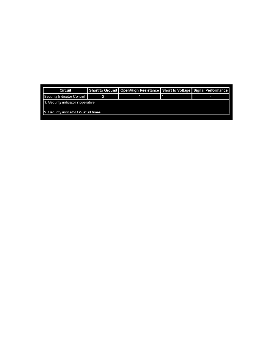
Diagnostic Fault Information
Circuit/System Description
The security indicator is controlled by the Body Control Module (BCM) based on commands from the immobilizer system or the Content Theft
Deterrent (CTD) system. With the ignition OFF, the security indicator is commanded by the CTD system. With the ignition ON, the security indicator is
commanded by the immobilizer system.
The security indicator is located in the Instrument Panel Cluster (IPC) and is supplied B+ at all times. When the immobilizer or CTD system requests the
indicator be commanded ON, the BCM grounds the security indicator control circuit, illuminating the indicator.
Circuit/System Verification
Ignition ON, command the security indicator ON and OFF with a scan tool. The security indicator should turn ON and OFF when changing between the
commanded states.
Circuit/System Testing
1. Ignition OFF, disconnect the harness connector at the IPC.
2. Connect a test lamp between the control circuit terminal 16 and B+.
3. Command the security indicator ON and OFF with a scan tool. The test lamp should turn ON and OFF when changing between the commanded
states.
^
If the test lamp is always ON, test the control circuit for a short to ground. If the circuit tests normal, replace the BCM.
^
If the test lamp is always OFF, test the control circuit for a short to voltage or an open/high resistance. If the circuit tests normal, replace the
BCM.
4. If all circuits test normal, replace the IPC.
Repair Instructions
Perform the Diagnostic Repair Verification after completing the diagnostic procedure. See: Powertrain Management/Computers and Control
Systems/Testing and Inspection/Diagnostic Trouble Code Tests and Associated Procedures/Verification Tests and Procedures