
Equinox FWD V6-3.0L (2010)
nut (2) onto the upper-most wheel stud.
5. Continue to hold the rotor secure and tighten the lug nut firmly by hand.
6. Install the remaining CH-45101-100 - Conical Brake Rotor Washers and lug nuts onto the wheel studs and tighten the nuts firmly by hand in a
star-pattern.
7. Using the CH-39544-KIT - Complete Torque Socket Set - 10 PCS , or equivalent, tighten the lug nuts in a star-pattern to specification, in order to
properly secure the rotor. Refer to Tire and Wheel Removal and Installation (See: Maintenance/Wheels and Tires/Service and Repair).
8. If the brake rotor has been REFINISHED or REPLACED with a new rotor, proceed to step 14.
9. If the brake rotor meets the following criteria, proceed to step 10.
*
The rotor is within specifications and is being REUSED.
*
The rotor has NOT been refinished.
*
The rotor does NOT exhibit thickness variation exceeding the maximum allowable level.
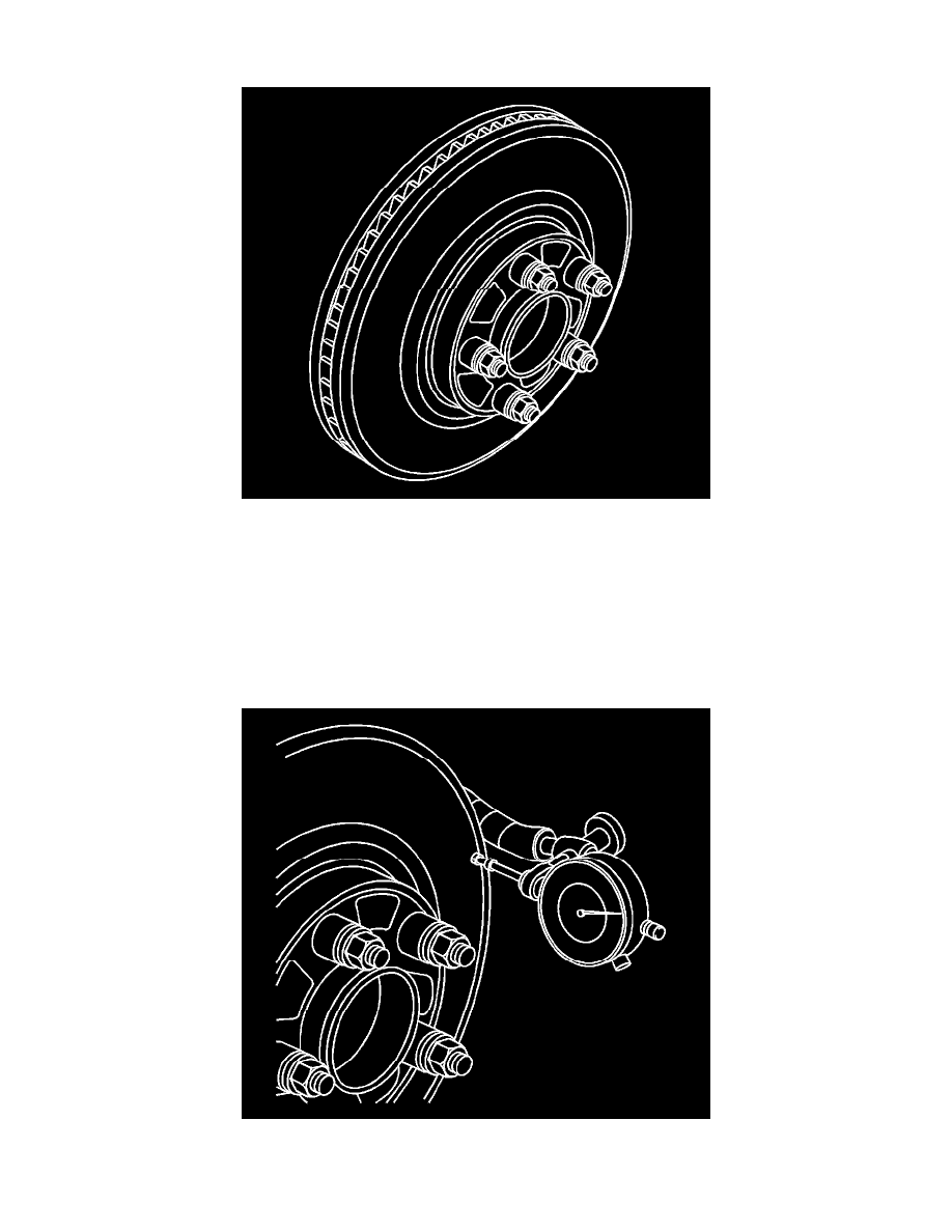
10. Mount a dial indicator, CH-45101 - Hub and Wheel Runout Gauge , or equivalent, to the steering knuckle and position the indicator button so it
contacts the brake rotor friction surface at a 90 degree angle, approximately 13 mm (0.5 in) from the outer edge of the rotor.
11. Measure and record the assembled LRO of the brake rotor.