
Equinox FWD V6-3.0L (2010)
‹› If each pair of serial data circuits is less than the specified range, replace the control module that was disconnected.
3. Connect the harness connectors at the control module that was disconnected.
4. Disconnect the harness connectors with the chassis high speed GMLAN serial data circuits at another control module, in the direction of the open
circuit.
5. Ignition OFF for 60 seconds, test for greater than 100k ohm between each pair of serial data circuits at the control module connector that was just
disconnected. Verify that one pair of serial data circuits are greater than 100k ohm.
‹› If each pair of serial data circuits is less than the specified range, replace the control module that was just disconnected.
6. Repeat step 3 until one of the following conditions are isolated:
*
An open/high resistance on the serial data circuit between 2 control modules or splice packs, if equipped
*
An open/high resistance on the serial data circuit between a control module and a terminating resistor
*
An open/high resistance terminating resistor
Repair Instructions
Perform the Diagnostic Repair Verification (See: Testing and Inspection/Diagnostic Trouble Code Tests and Associated Procedures/Verification Tests
and Procedures) after completing the repair.
*
GMLAN Wiring Repairs (See: Testing and Inspection/Component Tests and General Diagnostics/General Electrical Diagnostic
Procedures/Wiring Repairs/GMLAN Wiring Repairs)
*
Control Module References (See: Testing and Inspection/Programming and Relearning) for control module replacement, setup, and programming
Scan Tool Does Not Communicate with High Speed GMLAN Device
Scan Tool Does Not Communicate with High Speed GMLAN Device
Diagnostic Instructions
*
Perform the Diagnostic System Check - Vehicle (See: Testing and Inspection/Initial Inspection and Diagnostic Overview/Diagnostic System
Check - Vehicle) prior to using this diagnostic procedure.
*
Review Strategy Based Diagnosis (See: Testing and Inspection/Initial Inspection and Diagnostic Overview/Strategy Based Diagnosis) for an
overview of the diagnostic approach.
*
Diagnostic Procedure Instructions (See: Testing and Inspection/Initial Inspection and Diagnostic Overview/Diagnostic Procedure Instructions)
provides an overview of each diagnostic category.
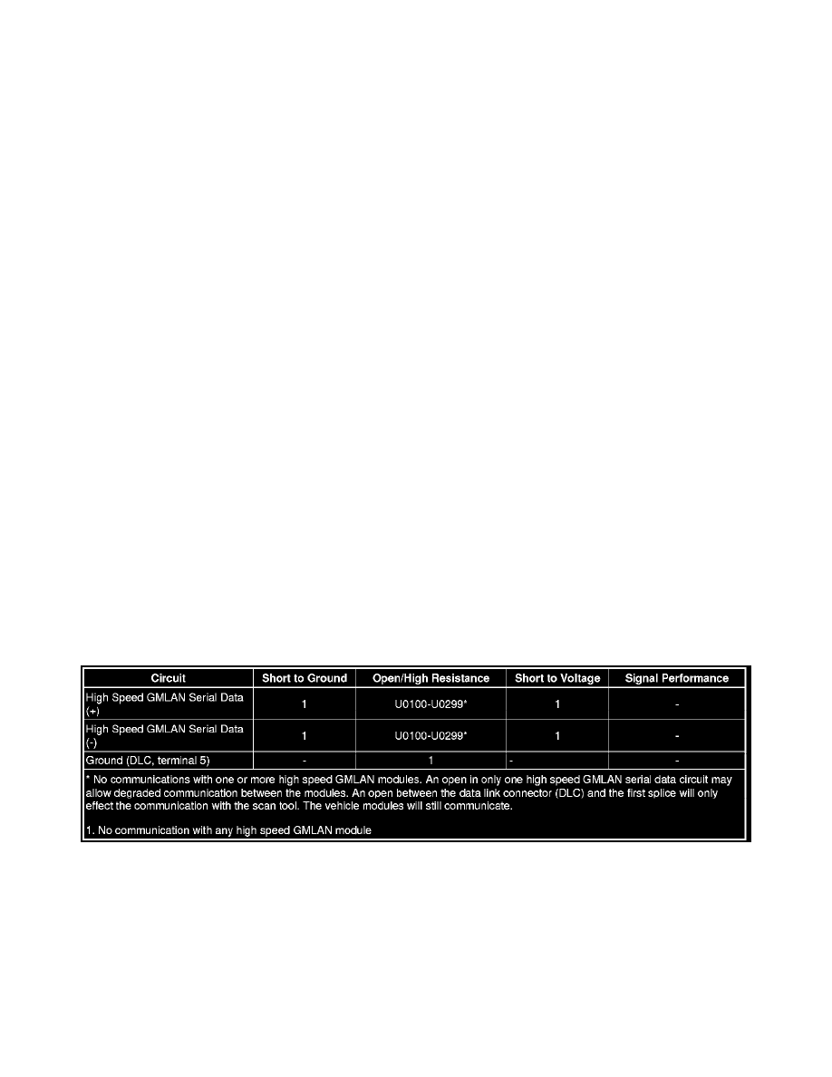
Diagnostic Fault Information
Circuit/System Description
The serial data is transmitted on two twisted wires that allow speeds up to 500 Kb/s. The twisted pair is terminated with two 120 ohms resistors, one is
internal to the engine control module (ECM) and the other can be a separate resistor in a connector assembly or in another control module. The resistors
are used as the load for the High Speed GMLAN buss during normal vehicle operation. The high speed GMLAN is a differential bus. The high speed
GMLAN serial data bus (+) and high speed GMLAN serial data (-) are driven to opposite extremes from a rest or idle level of approximately 2.5 V.
Driving the lines to their extremes, adds one volt to the high speed GMLAN serial data bus (+) circuit and subtracts one volt from the high speed
GMLAN serial data bus (-) circuit. If serial data is lost, control modules will set a no communication code against the non-communicating control
module. Note that a loss of serial data DTC does not represent a failure of the module that set it.
Diagnostic Aids