
Equinox FWD V6-3.0L (2010)
‹› If all control modules on the third splice pack do not communicate, test the serial data circuit between the second and third splice packs for an
open/high resistance. If the circuit tests normal, test the third splice pack for an open/high resistance. If the splice pack tests normal, replace
any module or component that may be between the those two splice packs.
3. Ignition OFF, disconnect the splice pack containing the serial data circuits to the modules that are not communicating.
4. Install a 3 A fused jumper wire between the splice pack connector serial data input terminal and a low speed GMLAN serial data circuit that is not
communicating:
5. Ignition ON, verify the scan tool communicates with the control modules connected to the low speed GMLAN serial data circuit.
‹› If any control module does not communicate, test each section of the serial data circuit for an open/high resistance. If the circuits test normal,
replace the control module that does not communicate when connected.
Repair Instructions
Perform the Diagnostic Repair Verification (See: Testing and Inspection/Diagnostic Trouble Code Tests and Associated Procedures/Verification Tests
and Procedures) after completing the repair.
*
GMLAN Wiring Repairs (See: Testing and Inspection/Component Tests and General Diagnostics/General Electrical Diagnostic
Procedures/Wiring Repairs/GMLAN Wiring Repairs)
*
Control Module References (See: Testing and Inspection/Programming and Relearning) for module replacement, setup, and programming
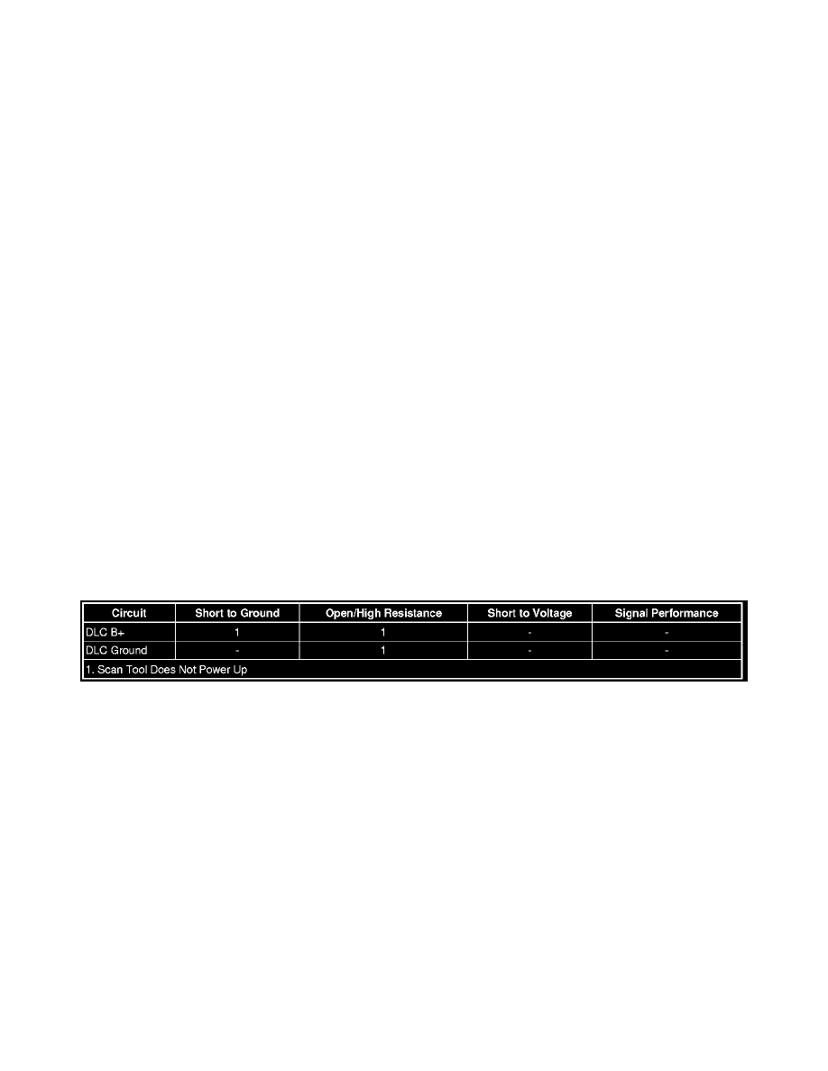
Scan Tool Does Not Power Up
Scan Tool Does Not Power Up
Diagnostic Instructions
*
Perform the Diagnostic System Check - Vehicle (See: Testing and Inspection/Initial Inspection and Diagnostic Overview/Diagnostic System
Check - Vehicle) prior to using this diagnostic procedure.
*
Review Strategy Based Diagnosis (See: Testing and Inspection/Initial Inspection and Diagnostic Overview/Strategy Based Diagnosis) for an
overview of the diagnostic approach.
*
Diagnostic Procedure Instructions (See: Testing and Inspection/Initial Inspection and Diagnostic Overview/Diagnostic Procedure Instructions)
provides an overview of each diagnostic category.
Diagnostic Fault Information
Circuit/System Description
The data link connector (DLC) is a standardized 16 cavity connector. Connector design and location is dictated by an industry wide standard, and is
required to provide the following:
*
Scan tool B+ voltage at terminal 16
*
Scan tool ground at terminal 4
*
Common ground at terminal 5
Diagnostic Aids
*
The scan tool will power up with the ignition OFF. Some modules however, will not communicate unless the ignition is ON and the power mode
master module sends the appropriate power mode message.
*
If the B+ circuit, ground circuits, and connections of the DLC are functioning properly, the malfunction must be due to the scan tool.
Reference Information
Schematic Reference
Data Communication Schematics (See: Diagrams/Electrical Diagrams)
Connector End View Reference
Component Connector End Views (See: Diagrams/Connector Views)