
Equinox FWD V6-3.4L (2007)
Crankshaft Position Sensor: Testing and Inspection
CRANKSHAFT POSITION SENSOR SYSTEM DIAGNOSIS
DIAGNOSTIC INSTRUCTIONS
-
Perform the Diagnostic System Check - Vehicle prior to using this diagnostic procedure. See: Testing and Inspection/Initial Inspection and
Diagnostic Overview/Diagnostic System Check - Vehicle
-
Review Strategy Based Diagnosis for an overview of the diagnostic approach.
-
Diagnostic Procedure Instructions provides an overview of each diagnostic category.
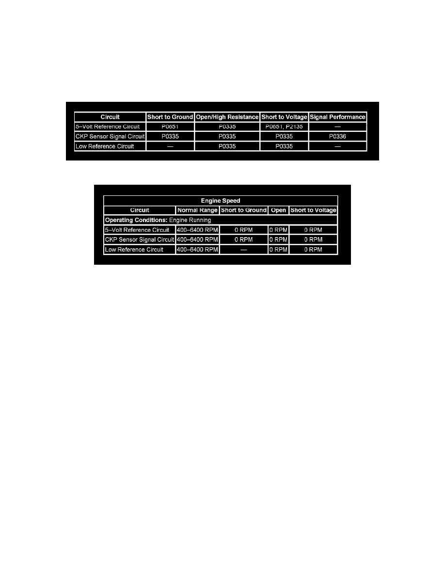
DIAGNOSTIC FAULT INFORMATION
TYPICAL SCAN TOOL DATA
CIRCUIT/SYSTEM DESCRIPTION
The crankshaft position (CKP) sensor circuits consist of an engine control module (ECM) supplied 5-volt reference circuit, low reference circuit and
an output signal circuit. The CKP sensor is an internally magnetic biased digital output integrated circuit sensing device. The sensor detects magnetic
flux changes of the teeth and slots of a 58-tooth reluctor wheel on the crankshaft. Each tooth on the reluctor wheel is spaced at 60-tooth spacing, with
2 missing teeth for the reference gap. The CKP sensor produces an ON/OFF DC voltage of varying frequency, with 58 output pulses per crankshaft
revolution. The frequency of the CKP sensor output depends on the velocity of the crankshaft. The CKP sensor sends a digital signal, which represents
an image of the crankshaft reluctor wheel, to the ECM as each tooth on the wheel rotates past the CKP sensor. The ECM uses each CKP signal pulse
to determine crankshaft speed and decodes the crankshaft reluctor wheel reference gap to identify crankshaft position. This information is then used to
determine the optimum ignition and injection points of the engine. The ECM also uses CKP sensor output information to determine the camshaft
relative position to the crankshaft, to control camshaft phasing, and to detect cylinder misfire.
DIAGNOSTIC AIDS
-
Inspect the CKP sensor connector and the ECM connector for corrosion.
-
With a DTC set, the engine may crank for an extended period of time at start-up.
CIRCUIT/SYSTEM VERIFICATION
If DTC P0641 or P0651 are set diagnose those DTCs first.
1. With the ignition OFF, inspect the engine wiring harnesses carrying the CKP sensor circuits for the following conditions:
-
Close routing of secondary ignition wires
-
Close routing of aftermarket electrical equipment
-
Close to solenoids, motors, and relays
-
Correct any wire harness routing or component placement conditions, if it is determined to be a possible source of electrical interference.
2. Start the engine. Using the Live Plot function on the scan tool, select the CMP parameter. Change the minimum spec to 400 RPM, and the
maximum spec to 4,000 RPM. Select the CKP sensor parameter. Change the minimum spec to 600 RPM, and the maximum spec to 3,300 RPM.
3. Observe the scan tool.
4. Quickly accelerate and release the accelerator pedal several time. Do not exceed 3,200 RPM. The graphed lines on the Live Plot display should
track together across the screen.
-
If the vehicle passes the Circuit/System Verification test, operate the vehicle within the Conditions for Running the DTC. You may also
operate the vehicle within the conditions that are captured in the Freeze Frame/Failure Records data list.
CIRCUIT/SYSTEM TESTING