
Express 1/2 Ton Van V6-4.3L VIN W (1999)
Scan Tool Inoperative (Part 2 Of 2)
CIRCUIT DESCRIPTION
Modules connected to the Class 2 serial data circuit monitor for serial data communications during normal vehicle operation. Operating
information and commands are exchanged among the modules. Connecting a Scan Tool to the DLC allows communication with the modules for
diagnostic purposes.
The diagnostic procedure assumes that all modules are powered. When you are uncertain whether this condition is met, perform the Diagnostic
System Check for the module in question. Diagnostic trouble codes (DTCs) may be set due to this symptom and during this diagnostic procedure.
Complete the diagnostic procedure in order to ensure that all the DTCs are diagnosed and cleared from memory.
DIAGNOSTIC AIDS
Use a J3561 6-A when probing or checking electrical connector terminals. The J3561 6-A prevents terminal damage and inspects for proper
terminal contact tension.
Disconnecting modules and turning the ignition switch to the RUN position may cause DTCs in these modules. Inspect for DTCs in which module
upon completion of the required repair.
Ensure that the theft deterrent system has not caused a Class 2 No Communication malfunction.
TEST DESCRIPTION
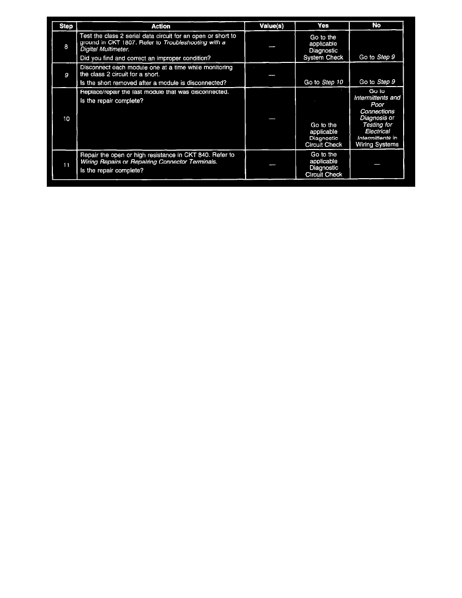
2. This step isolates the fault to the vehicle or the Scan Tool.
5. This step inspects the integrity of the ground to the Scan Tool.
6. This step inspects the integrity of the power to the Scan Tool.
9. This step inspects for a faulty module causing the Class 2 line to be shorted to ground.