
Express 1/2 Ton Van V8-305 5.0L VIN M SFI (1998)
Important:
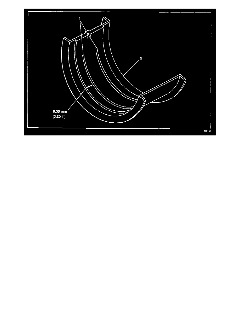
Do not loosen or attempt to service the number 1 (front) crankshaft (main) bearing cap or the number 1 crankshaft (main) bearings.
2.
Mark the number 2, 3, 4, and 5 crankshaft (main) bearing caps with position and direction. The crankshaft (main) bearing caps MUST be
reinstalled in the original position and direction.
3.
Support the crankshaft using a screw type jack and a block of wood.
3.1.
Position the screw type jack and the block of wood at the center of the crankshaft in order to properly support the crankshaft.
3.2.
Turn the screw of the screw type jack until the crankshaft is firmly seated against the crankshaft (main) upper bearings.
4.
Remove the number 5 crankshaft (main) bearing cap bolts, and the number 5 crankshaft (main) bearing cap with the crankshaft (main) lower
bearing.
5.
Using green plastigauge (designed for measuring 0.001-0.003 in. of clearance), lay two pieces, 2 inches in length, laterally along the number 5
lower crankshaft (main) bearing, 1/4 inch inboard from the insert outer edges. Re-install the bearing cap.
Tighten
5.1.
Tighten the bearing cap bolts on the first pass to 20 N.m (15 lb ft).
5.2.
Tighten the bearing cap bolts on the final pass to 73 degrees using the J 36660-A.
6.
Remove the number 5 cap and measure the plastigauge using the inch scale. All 1996-99 5.0L (L30) and 5.7L (L31) engines were built with 0.001
in. undersized number 5 crankshaft bearing inserts.
7.
If the measurement is:
^
Less than 0.0020 in. - Go To Step 8
^
0.0020 in. or greater but less than 0.0025 in. - Go To Step 9
^
0.0025 in. or greater but less than 0.0030 in. - Go To Step 10
^
.0.0030 in. or greater - Go To Step 11