
Express 1/2 Ton Van V8-305 5.0L VIN M SFI (1998)
To navigate through these "Cell" references start at the vehicle level and go to: Diagrams / Electrical Diagrams - for a complete list of the diagrams
available for the vehicle. Choose the system you are working on and view those diagrams.
Note: If unsure of the system - try utilizing the search feature. Type a component in the search feature that belongs to the system and when the
results are displayed note the path displayed. This will show the system the component belongs in.
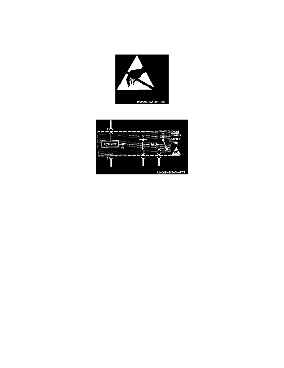
Electrostatic Discharge (ESD Sensitive Devices)
Electrostatic Discharge (ESD) Sensitive Device Symbol
Component (On Schematic) Indicated As ESD Sensitive
All Electrostatic Discharge (ESD) sensitive components contain Solid State circuits. The following information applies to all ESD sensitive devices. The
ESD symbol is used on schematics to indicate which components are ESD sensitive.
Handling Procedures
When handling an electronic part that is ESD sensitive, the service technician should follow these guidelines to reduce any possible electrostatic
charge build-up on the service technician's body and the electronic part in the dealership:
1. Always touch a known good ground before handling the part. This should be repeated while handling the part and more frequently after sliding
across the seat, sitting down from a standing position or walking a distance.
2. Avoid touching electrical terminals of the pan, unless so instructed by a written diagnostic procedure.
3. Do not open package of new part until it is time to install the part.
4. Before removing the part from its package, ground the package to a known good ground on the vehicle.
Measuring Procedures
1. Solid State circuits in electronic devices are shown greatly simplified.
2. Due to the simplification of the electronic devices on the schematics, resistance measurements could be misleading or could lead to
electrostatic discharge.
3. Only measure the resistance at the terminals of these devices when instructed by a written diagnostic procedure.
4. When using a voltmeter, be sure to connect the ground lead first.
On Board Diagnostics II (OBDII) Symbol