
Express 1/2 Ton Van V8-305 5.0L VIN M SFI (1998)
Throttle Position Sensor: Diagnostic Aids
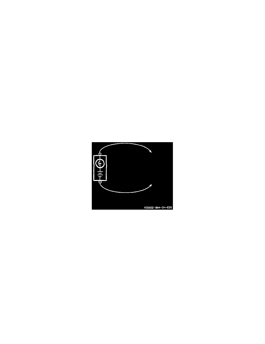
Test Lamp/Voltmeter
Use a test lamp to check for voltage. A Test Lamp (J 34142-B or equivalent) is made up of a 12-Volt light bulb with a pair of leads attached to
grounding one lead, touch the other lead to various points along the circuit where voltage should be present. When the bulb goes ON, there is voltage at
the point being tested.
A voltmeter can be used instead of a test lamp. While a test lamp shows whether or not voltage is present, a voltmeter indicates how much voltage is
present.
An increasing number of circuits include solid state control modules. One example is the Electronic Control Module (ECM). Voltages in these circuits
should be tested only with a 1O-megohm or higher impedance digital voltmeter or multi-meter (J 34029-A, J 39200 or equivalent.) Never use a test
lamp on circuits that contain solid state components, since damage to these components may result.
When testing for voltage or continuity at a connection, you do not have to separate the two halves of the connector. Unless you are testing a
"weather-pack" connector, you should probe the connector from the back. Always check both sides of the connector. An accumulation of dirt and
corrosion between contact surfaces is sometimes a cause of electrical problems.
Connector Test Adapters
A connector Adapter Kit is available (J 35616) for making tests and measurements at separated connectors. This kit contains an assortment of probes
which mate with many of the types of connectors you will see. Avoid using paper clips and other substitutes since they can damage terminals and cause
incorrect measurements.
Self-Powered Test Lamp
Self-Powered Test Lamp
Use a self-powered test lamp (J 21008-A or equivalent) to check for continuity. This tool is made up of a lamp bulb, battery and two leads. If the leads
are touched together, the bulb will light.
A self-powered test lamp is used only on an unpowered circuit. First disconnect the vehicle's battery, or remove the fuse which feeds the circuit you're
working on. Select two specific points along the circuit through which there should be continuity. Connect one lead of the self-powered test lamp to each
point. If there is continuity, the test lamp's circuit will be completed and the bulb will light.
Never use a self-powered test lamp on circuits that contain solid state components, since damage to these components may result.
Ohmmeter
An ohmmeter can be used instead of a self-powered test lamp. The ohmmeter shows how much resistance there is between two points along a circuit. LO
resistance means good continuity.
Circuits which include any solid state control modules, such as the Electronic Control Module (ECM), should be tested only with a 10-megohm or
higher impedance digital multimeter (J 34029-A, J 39200, or equivalent).
When measuring resistance with a digital multimeter, the vehicle battery should be disconnected. This will prevent incorrect readings.
Diodes and solid state components in a circuit can cause an ohmmeter to give a false reading. To find out if a component is affecting a measurement,
take a reading once, reverse the leads, then take a second reading. If the readings differ, the solid state component is affecting the measurement.