
Express 1/2 Ton Van V8-305 5.0L VIN M SFI (1998)
2. Mark the installed position of the rear propeller shaft.
IMPORTANT: Observe and mark the positions of all driveline components relative to the propeller shaft and axles prior to disassembly. These
components include the propeller shafts, drive axles, pinion flanges, output shafts, etc. All components must be reassembled in the exact
relationship to each as the components had prior to disassembly. Follow all specifications and torque values, as well as any measurements made
prior to disassembly.
3. Disconnect the propeller shaft.
^
Use a piece to tape in order to hold the bearing caps
^
Secure the propeller shaft up and out of the way in a manner that does not put unnecessary stress on the universal joints
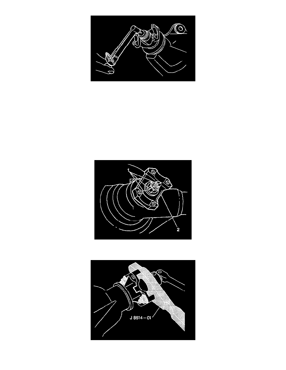
4. Measure the amount of torque required to turn the pinion using the J5853-B.
^
Record the torque measurement for reassembly
^
The measurement give the combined pinion bearing, seal, and carrier bearing preload.
5. Make an alignment mark (1) on the pinion stem, pinion flange (2), and pinion flange nut.
6. Record the number of exposed threads on the pinion stem for a reference.
7. Hold the pinion flange with the J8614-01.
8. Remove the pinion flange nut and washer.