
Express 1500 RWD V6-4.3L VIN X (2005)
Body Control Module: Scan Tool Testing and Procedures
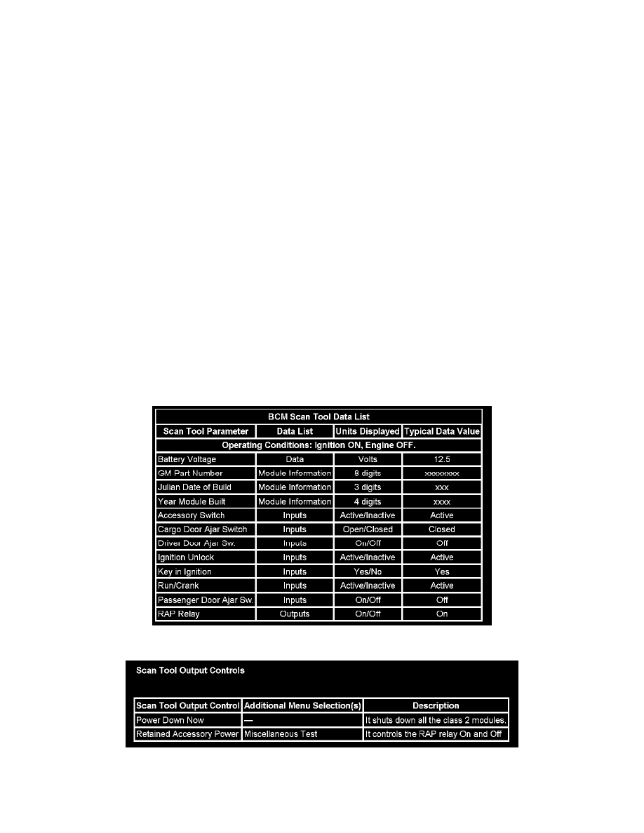
Scan Tool Data Definitions
SCAN TOOL DATA DEFINITIONS
Accessory Switch: Input from ignition switch Accessory circuit. Used to determine power mode. Hot in ACC and ON.
Battery Voltage: The scan tool displays 0.0-16.0 volts. The battery voltage input represents the system voltage measured at the BCM ignition feed
input.
Cargo Door Ajar Switch: Input from the cargo door showing the state of it.
Driver/Passenger Door Ajar Sw.: Input from the respecting door indicating door status.
GM Part Number: The module's part number.
Ignition Unlock: Input to the control module from the ignition switch indicating the Ignition 0 position. Switch closed (HOT) in ignition switch
positions UNLOCK, ACC, ON, and START.
Run/Crank: Input to the control module from the ignition switch indicating the Ignition 1 position. Switch closed (HOT) in ignition switch positions
ON and START.
Key in Ignition: Input from ignition switch indicating that the ignition key is inserted into the ignition switch. HOT with key in ignition switch.
Julian Date of Build: The day of the year when module was built.
RAP Relay: Output indicating the state of the RAP relay. It is On for all power modes except Off Awake.
Year Module Built: The year when module was built.
BCM Scan Tool Data List
Scan Tool Output Controls