
Express 1500 RWD V6-4.3L VIN X (2005)
45. Move the power source, 12 V minimum/2 A minimum, i.e., a vehicle battery, near the shorted ends of the driver side deployment harnesses.
46. Separate the ends of the steering wheel module deployment harness wires.
47. Connect the steering wheel module deployment harness wires to the power source in order to deploy the steering wheel module.
48. Disconnect the steering wheel module deployment harness wires from the power source.
49. Twist together one end of each wire of the steering wheel module on the driver side deployment harness in order to short the wires.
50. Remove the drop cloth from the vehicle.
51. Disconnect all harnesses from the vehicle.
52. Discard the harnesses.
53. Scrap the vehicle in the same manner as a non-SIR equipped vehicle.
54. If one or more of the inflator modules did not deploy, perform the following steps to remove the undeployed modules from the vehicle:
-
Inflatable Restraint Steering Wheel Module Replacement
-
Inflatable Restraint Instrument Panel Module Replacement
55. Contact the Technical Assistance Group for further assistance.
Deployment Procedures
DEPLOYMENT PROCEDURES
Inflator modules can be deployed inside or outside of the vehicle. The method used depends upon the final disposition of the vehicle. Review the
deployment procedures in order to determine which will work best in a given situation.
Steering Wheel Module Replacement
INFLATABLE RESTRAINT STEERING WHEEL MODULE REPLACEMENT
REMOVAL PROCEDURE
1. Disable the inflatable restraint steering wheel module. Refer to SIR Disabling and Enabling Zone 3.
CAUTION:
-
Refer to SIR Inflator Module Handling and Storage Caution in Service Precautions.
-
Refer to SIR Caution in Service Precautions.
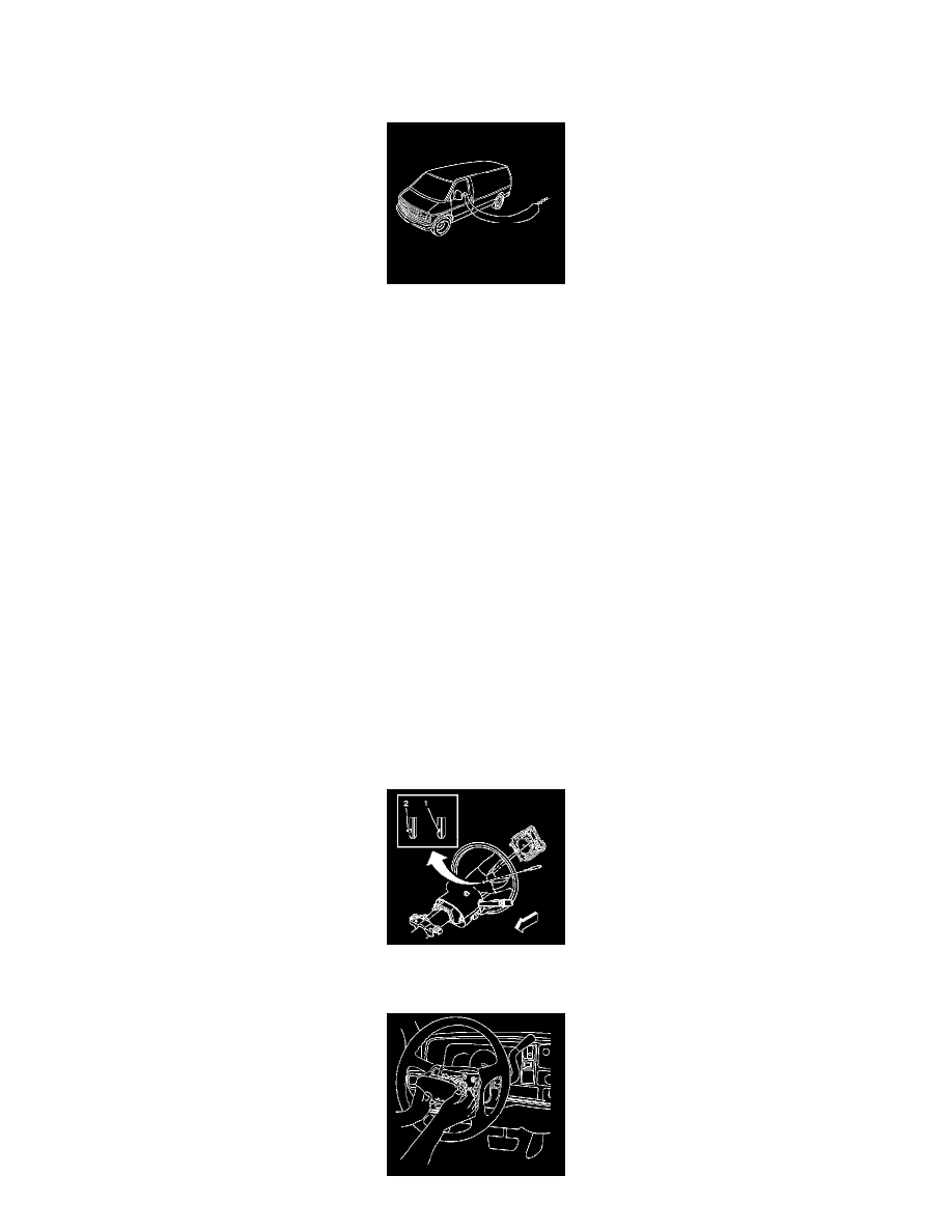
2. Using a blunt-ended tool, push the leaf spring fasteners (2) inward through the access holes. The access holes are located on both sides of the
steering wheel shroud.