
Express 1 Ton Van V8-5.7L VIN R (1999)
3. Use the following procedure in order to install the solenoid assembly:
3.1. Pivot the plunger of the solenoid assembly in order to engage the plunger to the shift lever in the gear reduction and drive group.
3.2. Position the solenoid mounting flange.
3.3. Install the solenoid mounting screws.
Tighten
Tighten the solenoid screws to 2.8 N.m (25 lb in).
4. Install the frame seal.
IMPORTANT: If you are replacing the armature bearings, install the bearings onto the armature. Refer to Armature Bearing Replacement.
5. Use the following procedure in order to install the armature assembly and the bearings into the gear reduction and drive group.
5.1. Ensure that the teeth align.
5.2. Seat the bearing on the armature shaft fully into the housing recess.
6. Use the following procedure in order to install the frame the field and the brush holder group.
6.1. Place the dowel pin into the hole in the armature support bracket of the gear reduction and drive group.
6.2. Position the frame the field and the brush holder group over the armature assembly.
6.3. Align the hole for the dowel pin.
6.4. Align the marks made during disassembly.
6.5. Seat the frame the field and the brush holder group into the gear reduction and drive group.
6.6. Twist the brush springs away from the brushes.
6.7. Slide the brushes in order to contact the commutator on the armature.
6.8. Release the brush springs in order to contact the ends of the brushes.
6.9. Verify that the brush spring tension is 44.5-49 N.m (10-11 lb).
6.10.If the brush spring tension is not correct, replace the brush springs.
IMPORTANT: The O-ring seal will damage easily during installation of the commutator end frame. In order to prevent damage to the O-ring
seal, use the following procedure.
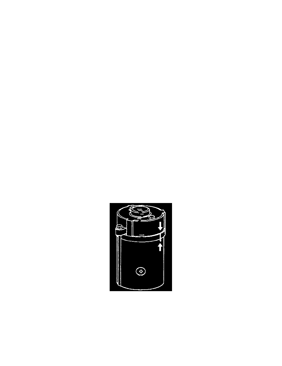
7. Use the following procedure in order to install the O-ring seal.
7.1. Install the O-ring seal onto the frame, field and brush holder group in the normal position. The O-ring seal is in the normal position when the
seal is against the shoulder on the field frame that will abut the installed commutator end frame.
7.2. Carefully roll the O-ring seal out of the normal position and up onto the major outer diameter of the field frame.
7.3. Allow the seal to remain on the outer diameter of the field frame until the commutator end frame is partially installed.
8. Use the following procedure in order to install the commutator end frame.
8.1. Align the marks on the commutator end frame and the frame and field assembly made at disassembly.
8.2. Position the commutator end frame onto the frame and field assembly.
8.3. Leave a gap slightly larger than the thickness of the O-ring seal.