
Express 1 Ton Van V8-5.7L VIN R (1999)
2. Use an RPM indicator in order to measure pinion speed.
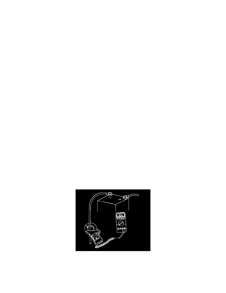
3. Connect the motor and an ammeter in series with the following components:
-
A fully charged battery (1) of the specified voltage
-
A switch in the open position from the solenoid battery terminal to the solenoid switch terminal.
4. Close the switch.
5. Compare the following measurements with the no load test specified values for the 28-MT Starter Motors in Starter Motor Usage (Load Test @ 10
Volts 28-MT).
-
RPM
-
Current
-
Voltage
6. Evaluate the measurements by understanding that the measurement is not necessary in order to obtain the exact voltage specified. A good reading
can be made by understanding that if the voltage is slightly higher, the RPM will be slightly higher and the current will remain basically unchanged
7. Use the following procedure in order to obtain the exact specified voltage (if desired):
7.1. Connect a carbon pile across the battery.
7.2. Compare the reduced voltage with the no load test specified values for the 28-MT and PG260 Starter Motors in Starter Motor Usage (Load
Test @ 10 Volts 28-MT).
8. Disconnect the circuit only with the switch open.
9. Use the following information in order to interpret the test results:
9.1. Rated current draw and no-load speed indicate normal condition of the starter motor.
9.2. Low free speed and high current draw indicate the following conditions:
^
Excessive friction Tight, dirty, or worn bearings, a bent armature shaft or loose pole shoes allow the armature to drag.
^
A shorted armature Inspect a shorted armature on a growler after disassembly.
^
Grounded armature fields Verify the grounded armature after disassembly.
9.3. Failure to operate with no current draw indicates the following conditions:
^
A direct ground A direct ground exists in the terminal or fields.
^
Seized bearings Seized bearings should have been noted by hand turning the armature by hand.
9.4. Failure to operate with no current draw indicates the following conditions:
^
An open field circuit An open field circuit can be tested after disassembly by inspecting the internal connections and tracing the circuit
with a J 39200 digital multimeter.
^
Open armature coils Inspect the commutator for badly burned bars.
^
Broken brush springs worn brushes High insulation between the commutator bars or other causes which would prevent proper contact
between the brushes and the commutator.
9.5. Low no-load speed and low current draw indicate a higher internal resistance due to the following conditions:
^
Poor connections
^
Defective leads
^
A dirty commutator
^
An open field circuit
^
Open armature coils
^
Broken brush springs, worn brushes
9.6. High free speed and high current draw indicate shorted fields. If shorted fields are suspected, replace the field coil assembly and inspect for
improved performance.
Starter No Load Test (PG260)
TOOLS REQUIRED:
-
J 39200 Digital Multimeter
-
J 35590 Adapters, or equivalent
NOTE: Never operate the starter motor more than 15 seconds at a time without pausing in order to allow it to cool for at least 2 minutes. Overheating
will damage the starter motor.