
Express 2500 V8-5.3L VIN T (2005)
18. Secure and insulate the connection using electrical tape.
19. Connect the deployment harness to the steering wheel module connector.
20. Route the deployment harness out of the vehicle's driver side.
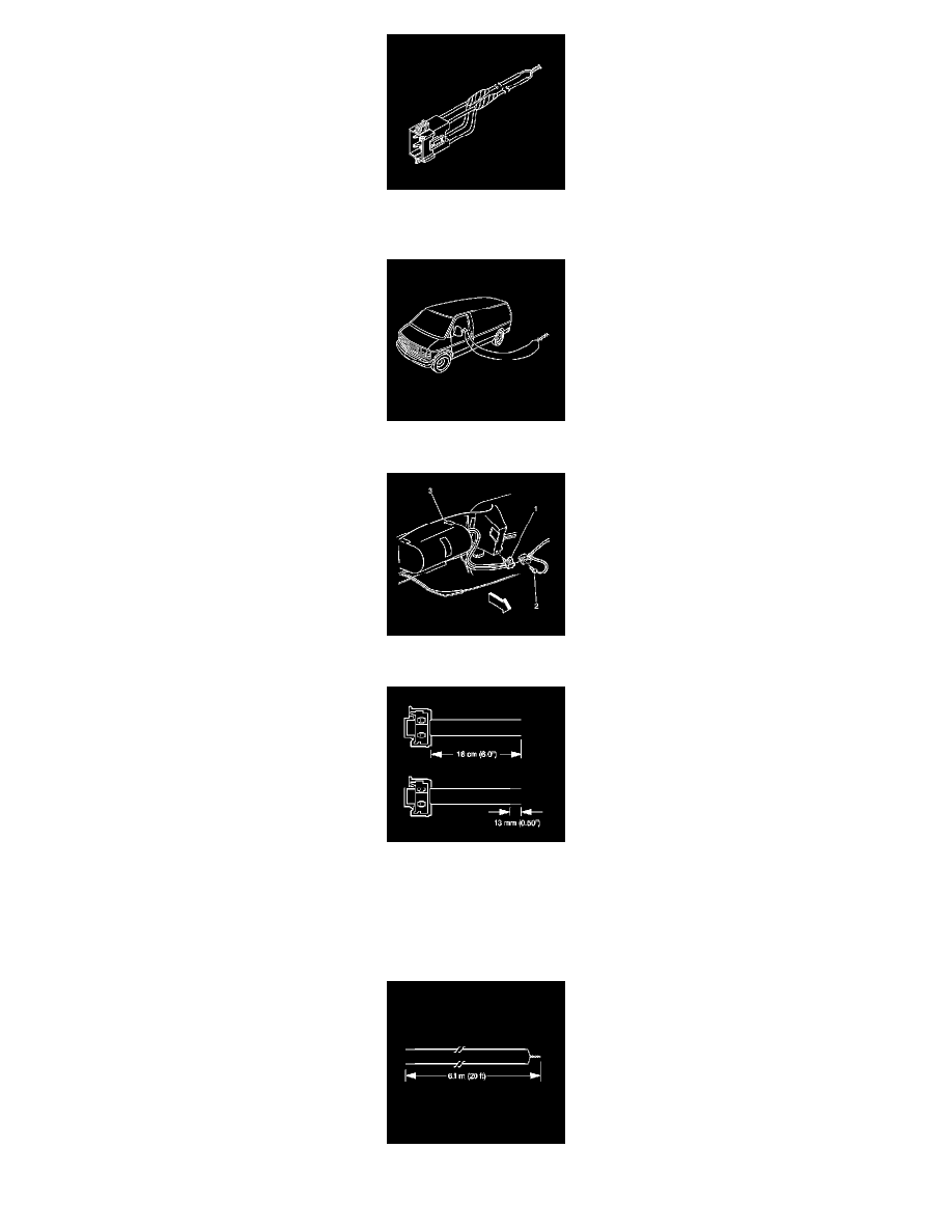
21. Disconnect the inflatable restraint I/P module connector (1) located under the instrument panel extension (3).
22. Cut the I/P module harness connector out of the vehicle, leaving at least 16 cm (6 in) of wire at the connector.
IMPORTANT: This vehicle is equipped with dual stage air bags. The steering wheel module and I/P module will each have 4 wires. Refer to SIR
Connector End Views for determining high and low circuits.
23. Strip 13 mm (0.5 in) of insulation from each of the connector wire leads.
24. Cut two 6.1 m (20 ft) deployment wires from a 0.8 mm (18 gage) or thicker multi-strand wire. These wires will be used to fabricate the