
Express 2500 V8-6.6L DSL Turbo (2010)
measurement was 0.127 mm (0.005 in), the 0.152 mm (0.006 in) correction plate would be used.
5. Determine the positioning for the correction plate (1) using the high spot mark (3) made during the brake rotor assembled LRO measurement
procedure.
Note:
*
Do NOT install used correction plates in an attempt to correct brake rotor assembled LRO.
*
Do NOT stack up, or install more than one correction plate onto one hub/axle flange location, in an attempt to correct brake rotor assembled
LRO.
6. Install the correction plate (1) onto the hub/axle flange, with the V-shaped notch (2) orientated to align with the high spot mark (3), that was
positioned to face upward.
7. Install the brake rotor to the hub/axle flange. Use the matchmark made prior to removal for proper orientation to the flange.
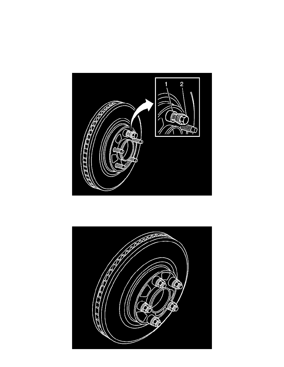
8. Hold the rotor firmly in place against the hub/axle flange and install one of the CH-45101-100 - Conical Brake Rotor Washers (1) and one lug nut
(2) onto the upper-most wheel stud.
9. Continue to hold the rotor secure and tighten the lug nut firmly by hand.