
Express 2500 V8-6.6L DSL Turbo (2010)
Oil Level Sensor: Testing and Inspection
VIN L
Engine Oil Level Sensor Diagnosis
Diagnostic Instructions
*
Perform the Diagnostic System Check - Vehicle (See: Testing and Inspection/Initial Inspection and Diagnostic Overview/Diagnostic System
Check - Vehicle) prior to using this diagnostic procedure.
*
Review Strategy Based Diagnosis (See: Testing and Inspection/Initial Inspection and Diagnostic Overview/Strategy Based Diagnosis) for an
overview of the diagnostic approach.
*
Diagnostic Procedure Instructions (See: Testing and Inspection/Initial Inspection and Diagnostic Overview/Diagnostic Procedure Instructions)
provides an overview of each diagnostic category.
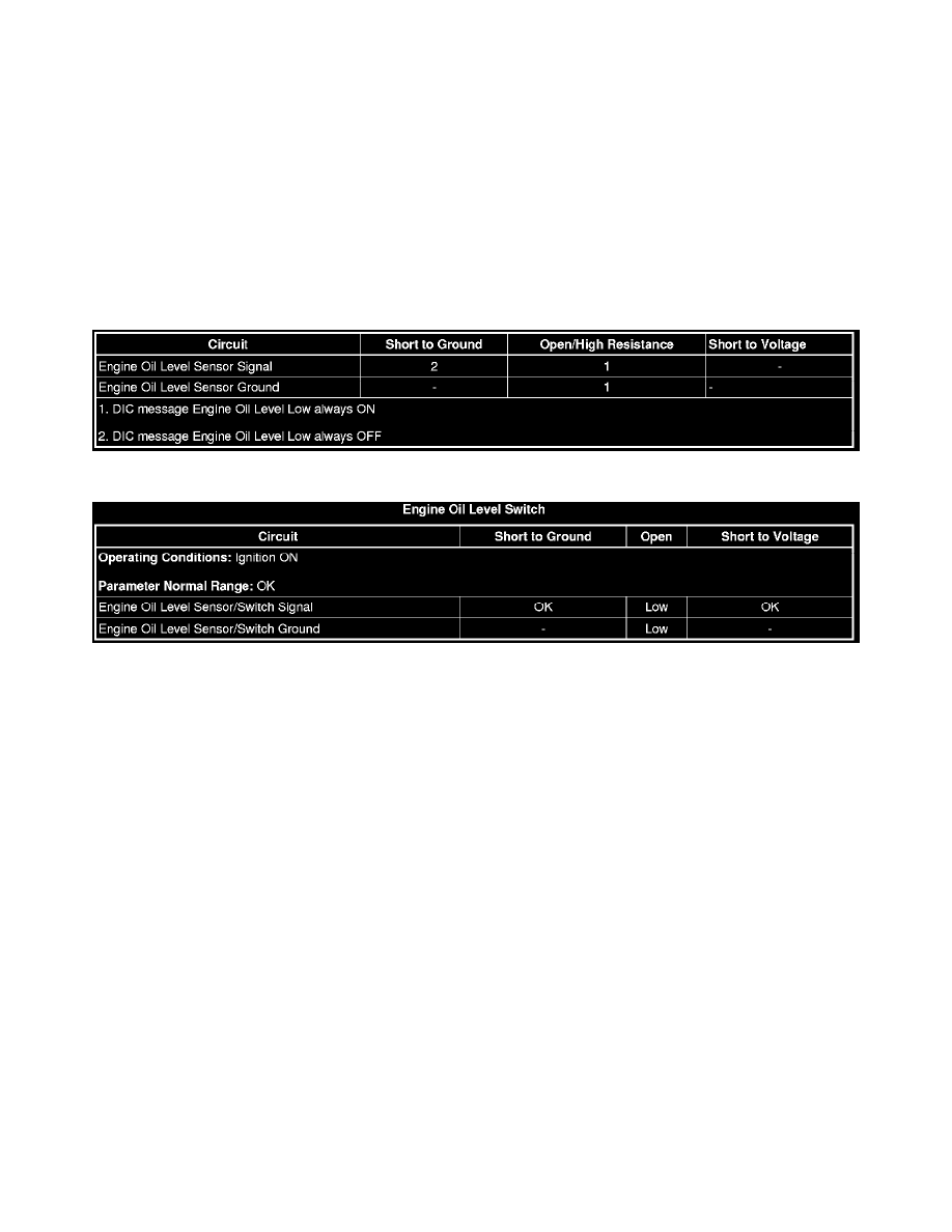
Diagnostic Fault Information
Typical Scan Tool Data
Circuit/System Description
The engine oil level sensor/switch is normally-closed with proper engine oil level. The switch opens when the engine oil level drops below a calibrated
level. The engine control module (ECM) monitors the engine oil level signal circuit when the ignition is ON, and the engine is OFF. With the switch in
the closed position, the ECM detects a low voltage on the signal circuit. With the switch in the open position, the ECM detects a high voltage on the
signal circuit. When high voltage is detected on the signal circuit, the ECM will send a serial data message to the instrument panel cluster (IPC). The IPC
will then display a message on the driver information center (DIC) or illuminate a low engine oil level lamp.
The following information determines the message sent from the ECM to the IPC:
*
The Low Engine Oil Level message lamp is displayed only after the ECM detects a high voltage on the signal circuit for three consecutive ignition
cycles, followed by an ignition OFF event from 15 minutes to greater than 50 minutes, depending on engine oil temperatures.
*
The Low Engine Oil Level message is turned OFF when the ECM detects a low voltage on the signal circuit after an ignition OFF event for greater
than 90 seconds, followed by an ignition ON event for less than 1 second.
Reference Information
Schematic Reference
*
Engine Mechanical Schematics (See: Diagrams/Electrical Diagrams)
*
Instrument Cluster Schematics (See: Diagrams/Electrical Diagrams/Instrument Panel, Gauges and Warning Indicators/System
Diagram/Instrument Cluster Schematics)
Connector End View Reference
Component Connector End Views (See: Diagrams/Connector Views/Connector End Views By Name)
Description and Operation
*
Instrument Cluster Description and Operation (See: Instrument Panel, Gauges and Warning Indicators/Description and Operation/Instrument
Cluster)
*
Indicator/Warning Message Description and Operation (See: Instrument Panel, Gauges and Warning Indicators/Description and