
Express 2500 V8-6.6L DSL Turbo (2010)
Circuit/System Description
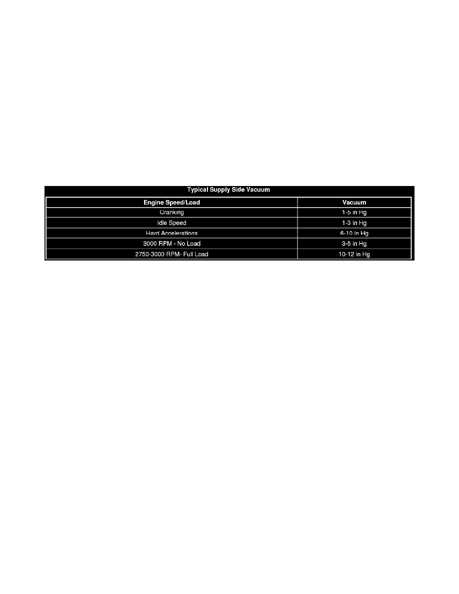
Fuel is drawn by the fuel injection pump through a pre-filter screen in the tank. Fuel flows to the diesel fuel conditioning module (DFCM), which
combines a water separator, an electric fuel prime pump, fuel heater element, and a filter element. The fuel is then delivered to a second screw on fuel
filter and the high-pressure pump. An integrated electric fuel prime pump is used to prime the fuel system after changing the fuel filter or servicing the
fuel system. The mechanical fuel injection pump at the front of the engine valley includes the fuel supply pump and the high-pressure pump.
High Pressure System
The much larger section of the fuel injection pump assembly is the high-pressure fuel injection pump. The pump is engine-driven by the camshaft gear.
From the high-pressure pump, the pressurized fuel flows to the left fuel rail. A balance pipe from the center of the left fuel rail then feeds the right fuel
rail. Each fuel rail supplies one bank of 4 fuel injectors. The fuel rail pressure (FRP) sensor is mounted in the right fuel rail.
Return System
Fuel is used to cool and lubricate the fuel injectors and fuel injection pump. The fuel return system is designed to return this fuel to the fuel tank. If the
high side fuel pressure becomes excessive, the fuel rail pressure relief valve releases the fuel into the fuel return system. The return fuel travels through
the diesel fuel conditioning module and the fuel cooler, then to the fuel tank.
Diagnostic Aids
A Cranks But Will Not Run or Hard Start symptom may exist if air is being drawn into the fuel injection system due to the following conditions:
*
Deformed or cut O-rings at the fuel supply line connections
*
Improperly seated fuel supply line fittings
*
Porous or weathered rubber fuel supply lines
Reference Information
Special Tools
*
CH-48027 Digital Pressure Gauge
*
J 44581 Fuel Line Disconnect Tool
*
EN-47969 Fuel Supply Diagnostic Hose
*
J-35555 Metal MityVac
Circuit/System Verification
Observe the Actual Fuel Rail Pressure parameter with a scan tool. During engine cranking, the pressure should be at least 10 MPa. With the engine
running at idle the pressure should be close to the Desired Fuel Rail Pressure. As the engine RPMs increase, the Desired Fuel Rail Pressure and the
Actual Fuel Rail Pressure should closely match each other.
Circuit/System Testing
1. Remove the engine cover. Refer to Engine Cover Replacement (See: Body and Frame/Access Cover/Service and Repair).
2. Clean all of the fuel lines between the fuel injection pump and the fuel injectors using brake cleaning solvent, and let dry.
Important: It may be necessary to remove engine components for the visual inspections.
3. Install the CH-48027 to the fuel system service port on the right front side of the engine.
Important: Fuel line connections should be inspected thoroughly for O-ring damage.
4. Command the fuel pump ON with a scan tool and observe the fuel pressure gauge to ensure that fuel pressure is present. Visually inspect the
engine and chassis for leaks or damage to the fuel hoses, fuel lines, and fuel system components.