
Express 2500 V8-6.6L DSL Turbo (2010)
High Idle Switch: Testing and Inspection
High Idle Switch Diagnosis
Diagnostic Instructions
*
Perform the Diagnostic System Check - Vehicle (See: Testing and Inspection/Initial Inspection and Diagnostic Overview/Diagnostic System
Check - Vehicle) prior to using this diagnostic procedure.
*
Review Strategy Based Diagnosis (See: Testing and Inspection/Initial Inspection and Diagnostic Overview/Strategy Based Diagnosis) for an
overview of the diagnostic approach.
*
Diagnostic Procedure Instructions (See: Testing and Inspection/Initial Inspection and Diagnostic Overview/Diagnostic Procedure Instructions
)provide an overview of each diagnostic category.
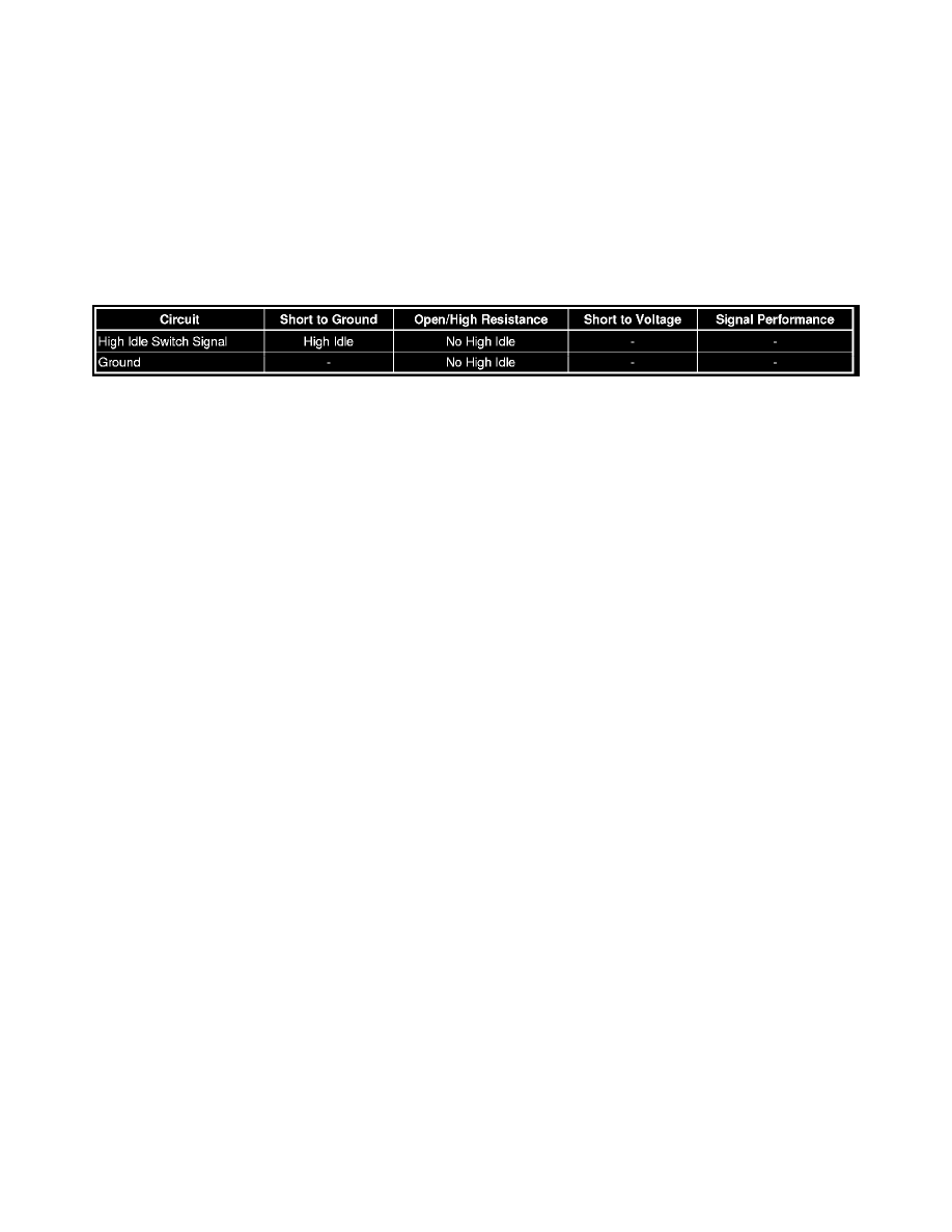
Diagnostic Fault Information
Reference Information
Schematic Reference
Engine Controls Schematics (See: Diagrams/Electrical Diagrams/Powertrain Management/System Diagram)
Connector End View Reference
Component Connector End Views (See: Diagrams/Connector Views/Connector End Views By Name)
Electrical Information Reference
*
Circuit Testing (See: Testing and Inspection/Component Tests and General Diagnostics/General Electrical Diagnostic Procedures/Circuit
Testing/Circuit Testing)
*
Connector Repairs (See: Testing and Inspection/Component Tests and General Diagnostics/General Electrical Diagnostic Procedures/Connector
Repairs/Connector Repairs)
*
Testing for Intermittent Conditions and Poor Connections (See: Testing and Inspection/Component Tests and General Diagnostics/General
Electrical Diagnostic Procedures/Circuit Testing/Testing for Intermittent Conditions and Poor Connections)
*
Wiring Repairs (See: Testing and Inspection/Component Tests and General Diagnostics/General Electrical Diagnostic Procedures/Wiring
Repairs/Wiring Repairs)
Scan Tool Reference
Control Module References (See: Testing and Inspection/Programming and Relearning)for scan tool information
Circuit/System Verification
Ignition ON, observe the scan tool High Idle switch parameter while exercising the switch. The reading should change between ON/OFF.
Circuit/System Testing
1. Ignition OFF, disconnect the harness connector at the high idle switch.
2. Test for less than 5 ohms between the ground circuit terminal A and ground.
‹› If greater than 5 ohms, test the ground circuit for an open/high resistance.
3. Ignition ON, verify the scan tool High Idle switch parameter is OFF.
‹› If not OFF, test the signal circuit for a short to ground. If the circuit tests normal, replace the ECM.
4. Install a 3A fused jumper wire between the signal circuit terminal C and ground. Verify the scan tool High Idle switch parameter is ON.
‹› If not ON, test the signal circuit for a short to voltage or an open/high resistance. If the circuit tests normal, replace the ECM.
5. If all circuits test normal, test or replace the high idle switch.
Component Testing