
Express 3/4 Ton Van V8-4.8L VIN V (2003)
7. Remove the C-clamp from the caliper.
8. Remove the brake caliper bracket mounting bolts.
Notice:
Support the brake caliper with heavy mechanic's wire, or equivalent, whenever it is separated from it's mount and the hydraulic flexible
brake hose is still connected. Failure to support the caliper in this manner will cause the flexible brake hose to bear the weight of the
caliper, which may cause damage to the brake hose and in turn may cause a brake fluid leak.
9. Remove the brake caliper and brake caliper bracket as an assembly and support with heavy mechanic's wire or equivalent. DO NOT disconnect the
hydraulic brake flexible hose from the caliper.
10. Remove the rotor retaining push nuts from the wheel studs, if applicable.
11. It may be necessary to strive the end of the hub or the rotor with a deadblow hammer to separate the rotor from the hub.
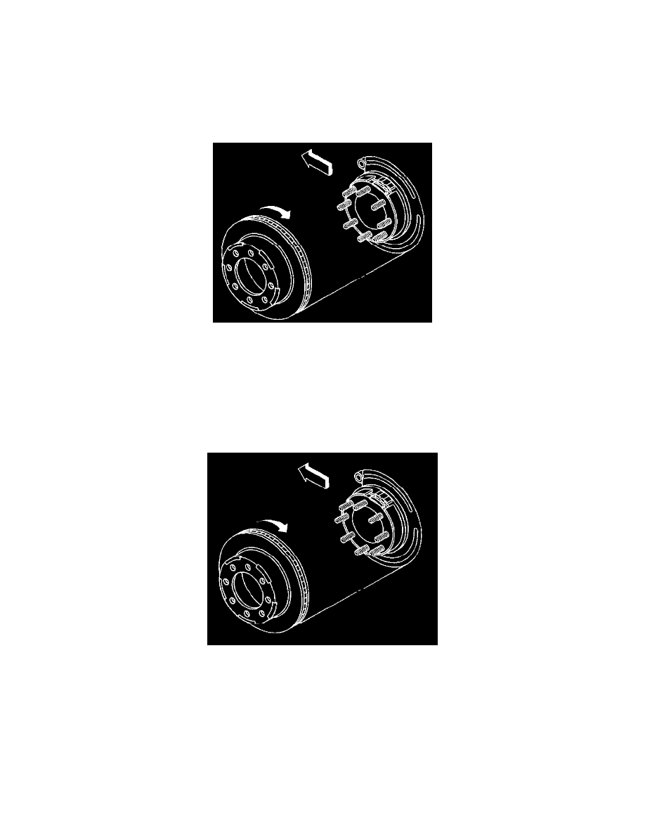
12. Remove the rotor by slowly turning the rotor while pulling the rotor aviary from the axle.
Installation Procedure
Important: Whenever the brake rotor has been separated from the hub axle flange any rust or contaminants should be cleaned from the hub axle flange
and the brake rotor mating surfaces, failure to do this may result in excessive assembled lateral runout (LRO) of the brake rotor, which
could lead brake pulsation.
1. Use the J42450-A to clean all rust contaminants from the mating surface of the hub flange.
2. Use the J41013 to clean all rust from the inside diameter inside diameter of the hat section of the brake rotor to prevent and any foreign material
from getting between the brake rotor and the hub flange
3. Inspect the mating surfaces of the hub flange and the rotor to ensure that there are no foreign particles of debris remaining.
4. Align the rotor to its original position on the hub if applicable, and install the rotor.
5. If the brake rotor was removed, and installed as part of a brake system repair measure the assembled lateral runout (LRO) of the brake rotor to
ensure optimum performance of the disc brakes.
6. If the brake rotor assembled LRO measurement exceeds the specification bring the LRO to within specifications.
7. Install the rotor by slowly turning the rotor while pushing the rotor towards the axle.