
Express 3500 V8-4.8L (2007)
32. Install the turn signal and multifunction switch assembly onto the steering column tilt head assembly.
Caution: Refer to SIR Inflator Module Coil Caution .
Important: Rest the electrical contact of the turn signal and multifunction switch assembly on the turn signal cancel cam assembly.
33. Screw the 2 pan head tapping screws into the turn signal and multifunction switch assembly.
Tighten the screws to 1 N.m (9 lb in).
34. Install the tilt spring only.
35. Install the ignition lock cylinder case.
36. Install the ignition lock cylinder.
37. Install the shift lever assembly.
38. Enable the SIR system. Refer to SIR Disabling and Enabling .
Lower Intermediate Steering Shaft Replacement
Lower Intermediate Steering Shaft Replacement
Tools Required
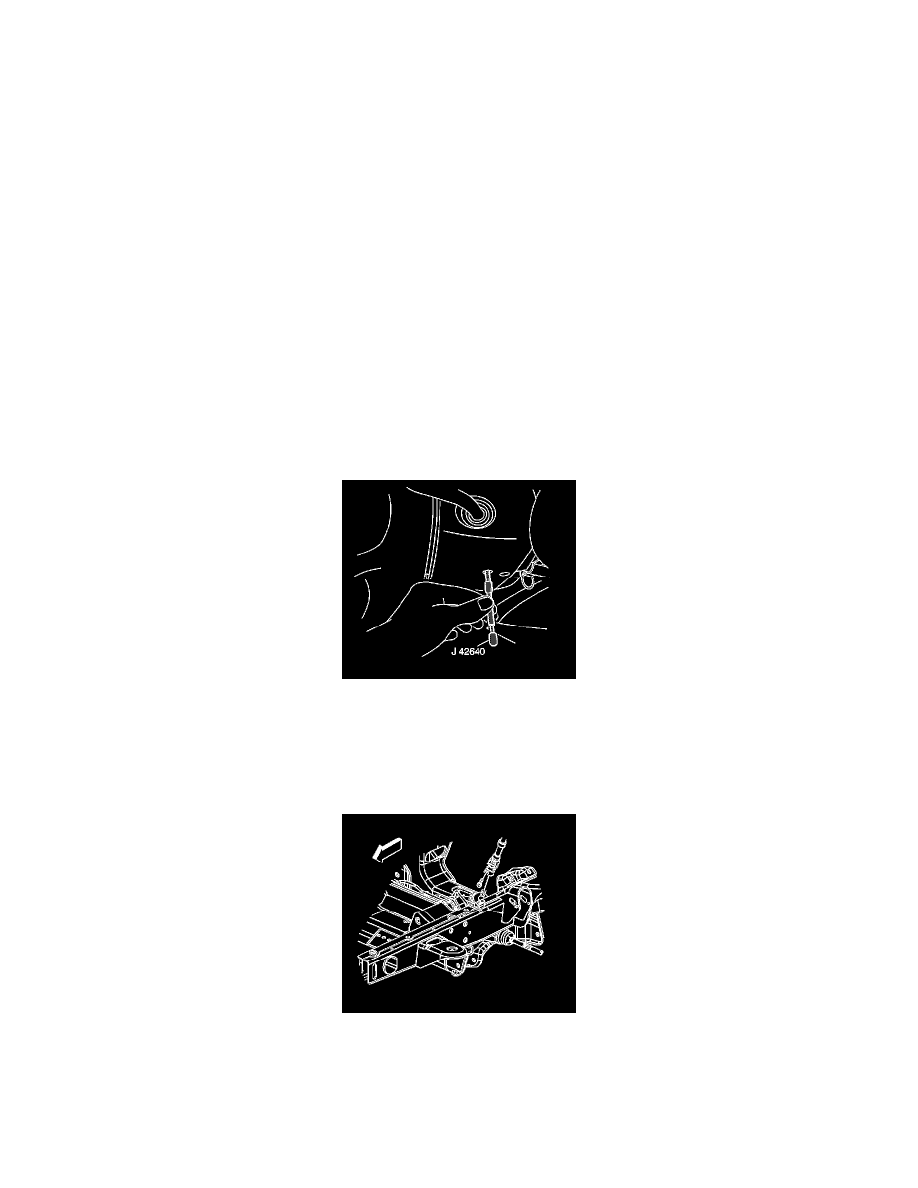
J 42640 Steering Column Anti-Rotation Pin
Removal Procedure
Notice: The wheels of the vehicle must be straight ahead and the steering column in the LOCK position before disconnecting the steering column
or intermediate shaft from the steering gear. Failure to do so will cause the SIR coil assembly to become uncentered, which may cause damage to
the coil assembly.
1. Install the J 42640 in the steering column lower access hole.
2. Raise and support the vehicle. Refer to Lifting and Jacking the Vehicle .
3. Mark the lower intermediate shaft to the power steering gear to aid in reassembly.
4. Remove the lower intermediate shaft to power steering gear retaining bolt.
5. Disconnect the lower intermediate shaft from the power steering gear.