
Express 3500 V8-6.0L (2010)
*
Diagnostic probe tool
*
Terminal release tool
*
Terminal/terminated lead part numbers
Note: Not using the proper test kit probe may cause damage to the terminal(s) that are probed.
2. Determine if a terminal is damaged.
*
Locate the diagnostic probe tool from the connector end view. The connector end view describes the color and part number to help the
technician find and use the correct tool.
*
Connect the probe tool to the Digital Multimeter.
*
Insert the probe tool into the cavity and follow the procedures from the Troubleshooting with a Digital Multimeter (See: Testing and
Inspection/Component Tests and General Diagnostics/General Electrical Diagnostic Procedures/Circuit Testing/Troubleshooting with a Digital
Multimeter).
3. Disconnect the connector body to perform the repair.
4. Use the following procedure to remove the terminal from the connector body.
Note: Several procedures for specific connector bodies are called out in the Wiring Repairs section.
*
The terminal position assurance (TPA) and connector position assurance (CPA) should be removed before releasing the terminal for the
connector body.
*
Look at the connector end view to locate the cavity of the damaged terminal and find the proper terminal release tool from the terminal release
tool kit.
Note: Using the incorrect terminal release tool can damage the connector body.
Note: Some terminals have a lever that must be disengaged before the terminal can be released.
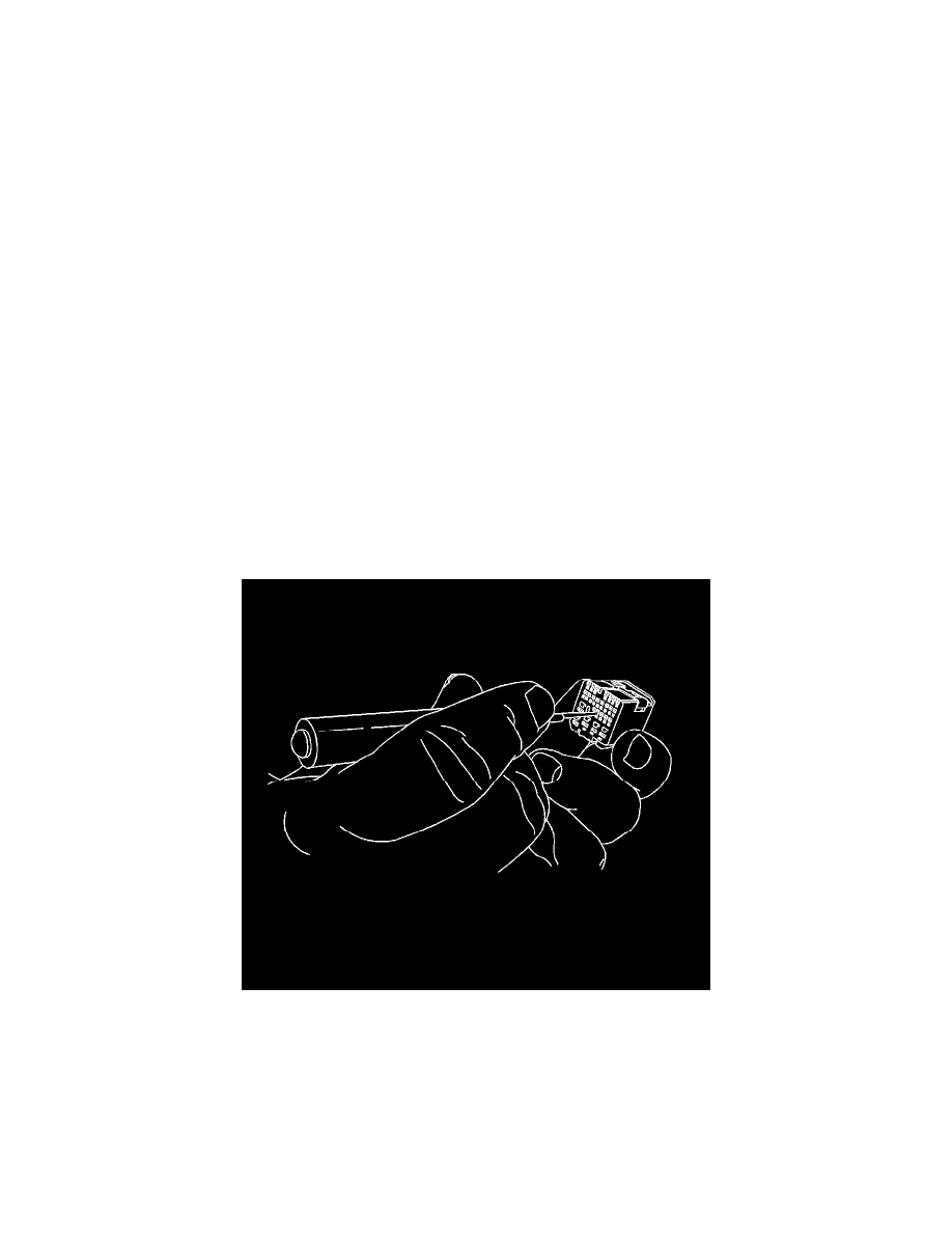
*
Insert the terminal release tool into the cavity.
5. Gently pull the wire out of the back of the connector.
6. Repair the terminal by following the Repairing Connector Terminals (See: Testing and Inspection/Component Tests and General
Diagnostics/General Electrical Diagnostic Procedures/Connector Repairs/Repairing Connector Terminals) procedure.
7. Insert the repaired terminal back into the cavity. Repeat the diagnostic procedure to verify the repair and reconnect the connector bodies.
Terminated Lead Repair
Terminated Lead Repair
Special Tools