
G 10 1/2 Ton Van V8-305 5.0L VIN H 4-bbl (1984)
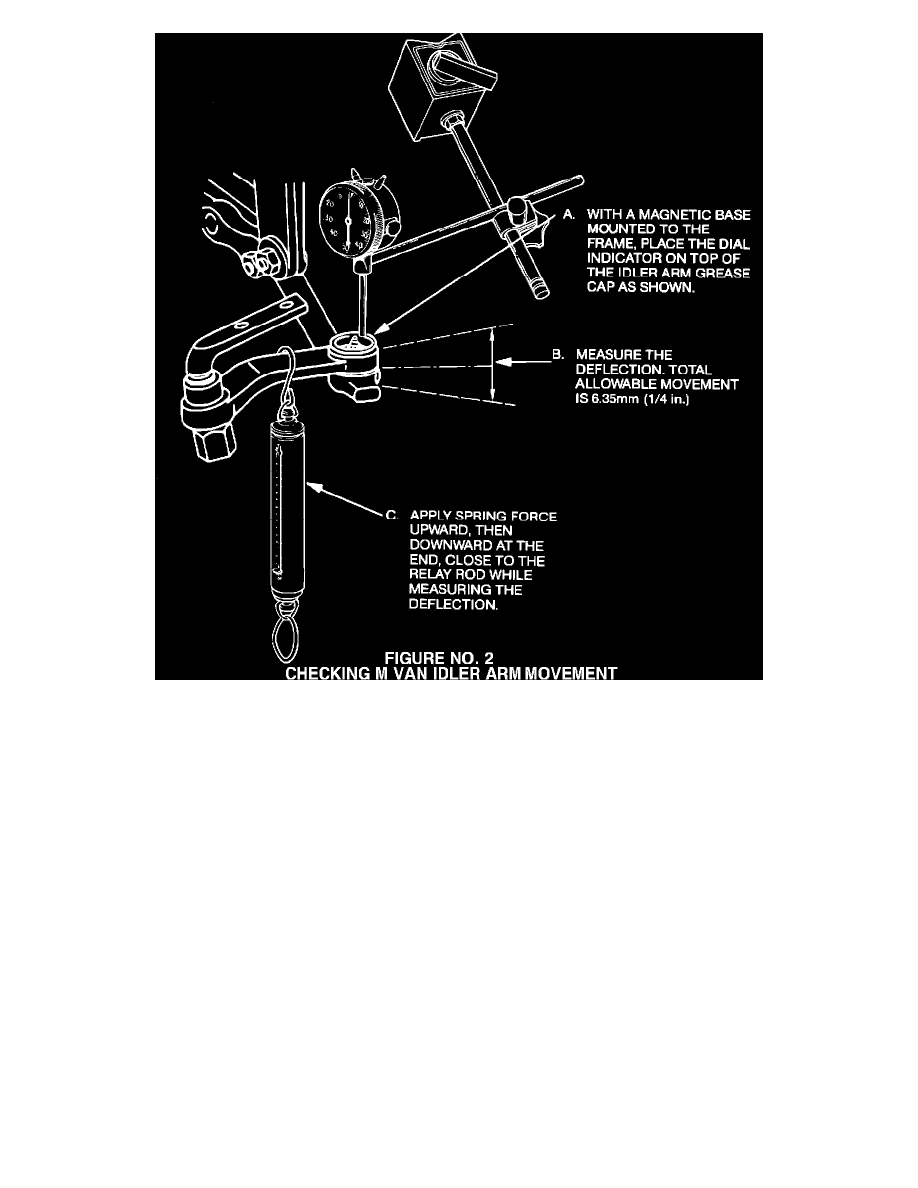
Figure No. 2 -Checking M Van Idler Arm Movement
INSPECTION PROCEDURE
1.
Raise the front of the vehicle and support it with jack stands at the lower control arms. The wheels must be free to rotate and the steering
mechanism free to turn.
2.
Position the wheels straight ahead.
3.
Place the dial indicator on top of the idler arm grease cap as shown in Figures No. 1 and 2 when measuring the deflection of the idler arm.
4.
FOR G VANS - Place a spring scale at the relay rod end of the idler arm (Figure No. 1). Using the spring scale, exert 110 N (25 lbs.) force
forward then rearward while measuring the total distance the arm moves.
FOR M VANS - Place a spring scale at the relay rod end of the idler arm (Figure No. 2).
Using the spring scale, exert 110 N (25 lbs) force upward then downward while measuring the total distance the arm moves.
5.
The allowable deflection is +/- 3.18 mm (1/8 inch) each direction for a total of 6.35 mm (1/4 inch).
6.
Replace only those idler arms which exceed a total movement of 6.35 mm (1/4 inch).
It is important to ensure that the correct load (force) is applied when making the measurements with the dial indicator. Using too much force will
cause movement in excess of the allowables given, even on a serviceable arm. Moving the front tire and wheel assemblies back and forth to cause
the idler arms to move is NOT an acceptable method for making this check. There is no way to determine the amount of force being applied to the
arm using this method.