
G 1500 1/2 Ton Van V6-4.3L VIN W (1997)
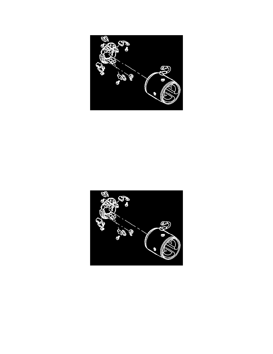
4. Frame, field, and brush holder group.
A. Place the dowel pin in the hole in the armature support bracket of the gear reduction and drive group.
B. Position the frame, field, and brush holder group over the armature assembly, align the hole for the dowel pin and marks made prior to
disassembly, and seat in the gear reduction and drive group.
Frame, Field, And Brush Holder Group
C. Twist the brush springs away from the brushes. Slide the brushes in to contact the commutator on the armature, and release the brush springs to
contact the ends of the brushes.
^
Brush spring tension should be 44.5 to 49 N (10-11 lbs). If not, replace the springs before proceeding.
5. O-ring seal.
Important
^
The O-ring seal can easily be damaged during installation of the commutator end frame. To prevent such damage, install the O-ring seal as
described in the following steps:
A. Install the O-ring seal on the frame, field, and brush holder group so that it is against the shoulder on the field frame that will abut the
commutator end frame when installed. This is the normal installed position of the O-ring seal.
B. Carefully roll the O-ring seal out of its normal installed position up onto the major outer diameter of the field frame. Allow the seal to
remain in this position until the commutator end frame is partially installed.
Frame, Field, And Brush Holder Group
6. Commutator end frame.