
G 20 Van V6-262 4.3L (1985)
emission label.
8.
Repeat steps 3 and 4. If unable to obtain specified dwell reading, proceed as follows:
a. If reading is below 25°, turn mixture screws counterclockwise 1 turn, then repeat steps 3 and 4.
b. If reading is above 35°, turn mixture screws clockwise 1 turn, then repeat steps 3 and 4.
c. If unable to adjust dwell to specifications, or if reading does not fluctuate, refer to C3 System Section.
9.
Stop engine. Seal mixture screw cavities with RTV sealer and install bleed valve cover.
10.
Reinstall air cleaner and reconnect vacuum hoses, then check curb idle speed.
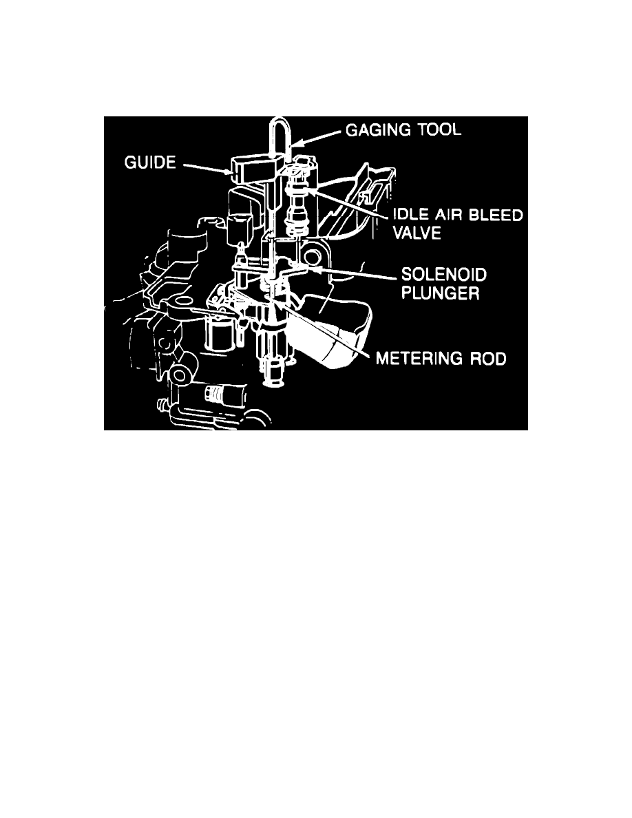
Fig. 8 Idle air valve adjustment. V6-229 & 231 w/E2MC-ME carburetor
MIXTURE ADJUSTMENT B
1.
Install gauging tool J-33815-2 or equivalent in ``D'' shaped hole on throttle side of air horn, with end of tool positioned above open cavity next to
idle air bleed valve, Fig. 8.
2.
Hold gauge down lightly to bottom MC solenoid plunger and adjust idle air bleed valve so that tool will pivot over and just contact top of valve.
Remove gauging tool.
3.
Remove plugs covering idle mixture adjusting screws as outlined under ``Concealment Plug Removal'' in the appropriate carburetor section. Turn
mixture screws in (clockwise) until lightly seated, then back screws out 3 turns.
4.
Reinstall carburetor using a new gasket, with air cleaner removed and vacuum hoses disconnected and plugged as outlined on underhood vehicle
emission label.
5.
Start engine and run until it reaches normal operating temperature and dwell begins to fluctuate.
6.
Place automatic transmission in drive (manual transmission in neutral) and adjust mixture screws equally to obtain a fluctuating dwell reading
between 25° and 35° (as close to 30° as possible). Turn mixture screws equally, 1/8 turn per adjustment, allowing time between adjustments for
engine to stabilize. If dwell reading is below 25°, turn screws counterclockwise; if reading is above 35° turn screws clockwise.
7.
If unable to obtain specified dwell reading, refer to ``System Performance Check'' as outlined in the C3 System Section.
8.
Stop engine. Seal mixture screw cavities with RTV sealer and install idle air bleed valve cover.
9.
Install air cleaner and reconnect vacuum hoses, then ensure curb idle speed is within specifications.
V6-262 W/M4MC, M4ME, M4MED & M4MEF Carburetors
LIGHT DUTY EMISSIONS VEHICLES
Idle mixture adjustment requires artificial propane enrichment. Propane enrichment tool J-26911 or equivalent, is required to adjust idle mixture. Air
cleaner must remain in place during adjustments. A/C control, if equipped, must be in Off position.
1.
Disconnect and plug vacuum hoses as directed on vehicle emission label.
2.
Connect tachometer to engine following tool manufacturer's instructions, then start engine and allow to reach normal operating temperature.
3.
Check and, if necessary, adjust ignition timing and curb idle speed to specification.
4.
Remove crankcase ventilation tube from air cleaner, then insert hose with rubber stopper from propane valve into opening in air cleaner. Propane
cylinder must remain upright during adjustments, and cylinder must be adequately filled to ensure correct adjustment.
5.
Set parking brake and block drive wheels, then place transmission in Drive (manual transmission in Neutral).