
G 20 Van V6-262 4.3L VIN Z (1993)
A.
The antenna should be a permanent-mount type located in die center of the roof or center of the rear deck lid. Glass mounted antennas
should be kept as high as possible in the center of the rear window or windshield. If a magnet-mount antenna is used, cam should be taken to
mount the antenna in the same location as a permanent-mount type. If a disguise-mount antenna is used, great care should be taken to shield
the tuning network from vehicle electronics and wiring, or to mount the tuning network in an area completely clear of vehicle electronics
and wiring.
B.
Standard metal mount antennas may be mounted on a vehicle with nonmetallic body panels by two methods. Most nonmetallic skinned
vehicles have metal frames underneath. Mounting the antenna near a metal frame wetion and bonding the antenna mount to the frame with a
short metal strap will provide die groundplane connection. Some antenna manufacturers offer "groundplane kits" that consist of self
adhesive metal foil that may be attached to the body panel to provide the groundplane for die antenna.
C.
Some vehicles use glass that contains a thin metallic coating for defrosting or to control solar gain. Glass mount antennas will NOT function
when mounted on this type of glass. Consult your GM dealer or owner's manual to determine if this glass is installed on your vehicle.
D.
Each vehicle model and body style reacts to radio frequency energy differently. When dealing with an unfamiliar vehicle, it is suggested that
a magnetic-mount antenna be used to check the proposed antenna location for unwanted effect on the vehicle. Antenna location is a major
factor in these effects.
3.
Antenna Cable Routing
A.
Always use a high quality coax (at least 95 % shield coverage) located away from the Engine Control Module and other electronic modules.
B.
Care should be taken to maintain as great a distance as possible between any vehicle wiring and the feedline.
4.
Antenna Tuning
It is important that the antenna be tuned properly and reflected power be kept to less than 10% (VSWR less than 2:1).
5.
Radio Wiring and Connection locations
A.
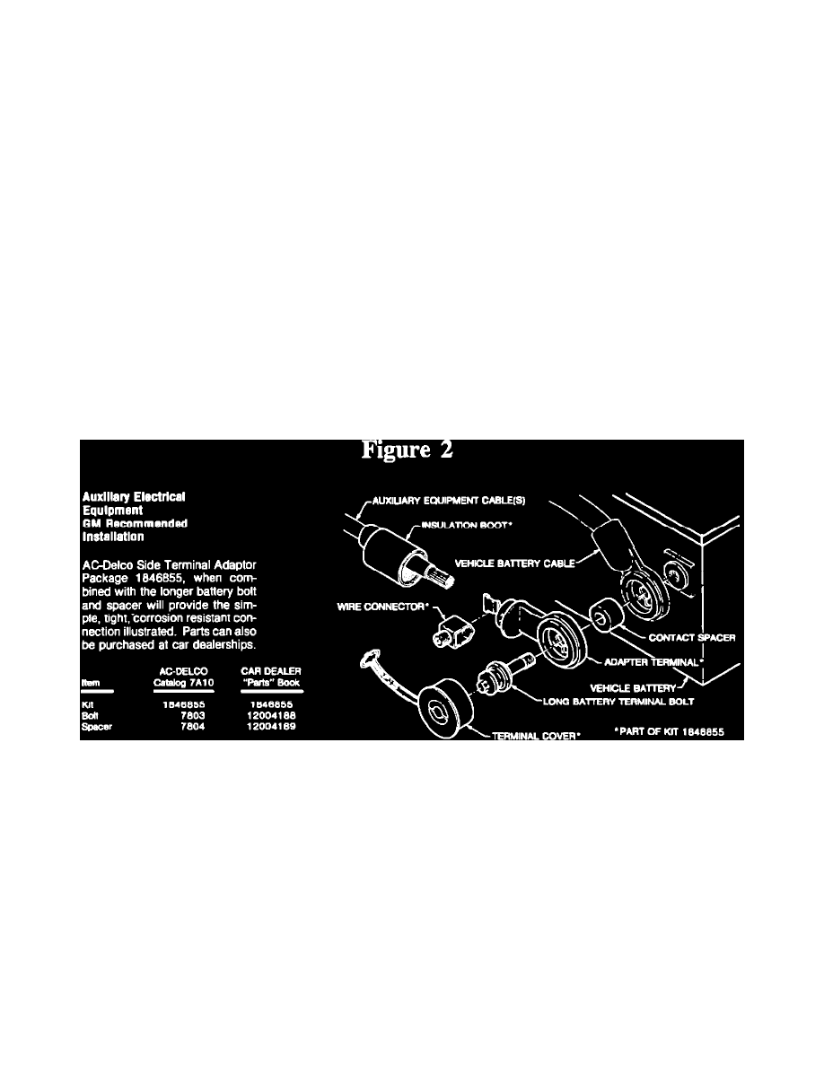
BOTH Transceiver power lead connections should be nude directly to the battery itself. On vehicles equipped with a "jump start terminal',
the positive lead may be connected to the terminal, but the negative lead should still be connected to the battery. GM approved methods of
connecting auxiliary wiring to a side terminal battery include the adapter package illustrated in Figure 2, NAPA-Belden replacement battery
bolts (part # 728198), or drilling and tapping the hex end of the original battery bolts 10-32 X 3/8' deep.
NOTE:
It is recommended that a fuse be placed in the transceiver negative lead to prevent possible transceiver damage in the event the battery to
engine-block ground lead is inadvertently disconnected.
For ONE-PIECE TRANSCEIVERS where ignition switch control is desired, a 12 Volt power contactor must be installed in the transceiver
positive lead. The contactor should be located at the vehicle battery with the coil of the contactor driven through an appropriate in-line fuse
from an available accessory circuit or ignition circuit not powered during cranking. The contactor coil must return to battery negative.
B.
Any negative lead from a handset or control unit must return to battery negative. It is preferable that the positive lead for a handset or
control unit be connected directly to the battery. It is recommended that the handset or control unit positive and negative leads be
appropriately fused separately from the transceiver positive and negative leads. N ignition switch control is desired, the handset or control