
G 20 Van V6-262 4.3L VIN Z (1993)
(ECM), should be tested only with a 10-megaohm or higher impedance digital multimeter.
When measuring resistance with a digital multimeter, the vehicle Battery should be disconnected. This will prevent incorrect readings. Digital
meters apply such a small voltage to measure resistance that the presence of voltages can upset a resistance reading. Diodes and solid state
components in a circuit can cause an ohmmeter to give a false reading. To find out if a component is affecting a measurement, take a reading once,
reverse the leads and take a second reading. If the readings differ, the solid state component is affecting the measurement.
FUSED JUMPER WIRE
A fused jumper is available with small clamp connectors providing adaptation to most connectors without damage. This fused jumper wire is
supplied with a 20 amp fuse which may not be suitable for some circuits. Do not use a fuse with a higher rating than the fuse that protects the
circuit being tested.
CAUTION: A fused jumper may not protect solid state components from being damaged.
SHORT FINDER
Short Finders are available to locate hidden shorts to ground. The short finder creates a pulsing magnetic field in the shorted circuit and shows you
the location of the short through body trim or sheet metal.
FUSE TESTER
A simple tester can detect a blown fuse. To check a fuse, the tester is applied directly to the fuse in the Fuse Block. Two probes contact the fuse,
either into the slots of a flat fuse or to the metal ends of a glass fuse. With power on, a red LED in the tester lights if the fuse is open. The handle
of the tester is a tool for removing either type of fuse.
Handling and Measuring Procedures
Fig. 1 ESD Symbol
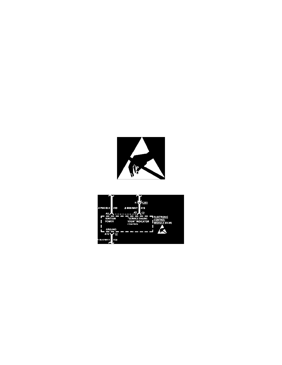
Fig. 2 Typical Schematic W/ESD Symbol
ELECTROSTATIC DISCHARGE (ESD) SENSITIVE DEVICES
All ESD sensitive components are Solid State and the following information applies to them. The ESD symbol, Fig. 1, is used on schematics to
indicate which components are ESD sensitive, Fig. 2. When handling any electronic part, the service technician should follow the guidelines
below to reduce any possible electrostatic charge build-up on the service technician's body and the electronic part in the dealership. If it is not
known whether or not a component is ESD sensitive, assume that it is.
HANDLING PROCEDURES
1. Always touch a known good ground before handling the part. This should be repeated while handling the part and more frequently after sliding
across the seat, sitting down from a standing position or walking the distance.
2. Avoid touching electrical terminals of the part, unless so instructed by a written diagnostic procedure.
3. When using a voltmeter be sure to connect the ground lead first.
4. Do not open package until it is time to install the part.
5. Before removing the part from its package, ground the package to a known good ground on the vehicle.
MEASURING PROCEDURES
The circuits shown within the boxes are greatly simplified. Do not troubleshoot by measuring resistance at any terminal of these devices unless so
instructed by a written diagnostic procedure. Due to the simplification of the schematics, resistance measurements could be misleading, or could
lead to electrostatic discharge.