G 20 Van V6-262 4.3L VIN Z (1993)

bearing fully into the hub. The Installer will apply force to the outer race of the bearing if used.
3. Using a center punch with a 45° angle point. stake 1.1-1.4mm (0.045-055" deep) the bearing in three places 120° apart, but do not stake too
deeply to avoid distorting the outer race of the bearing.
4. Replace rotor and bearing assembly.
On-Vehicle
A.
Position the Rotor and Bearing assembly on the front head.
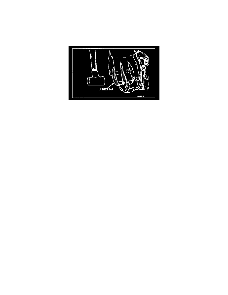
Installing Rotor And Bearing Assembly (On-Vehicle)
B.
With Rotor & Bearing Installer J 26271-A (without driver handle) in position and Rotor and Bearing assembly aligned with the Front Head as
shown in, drive the assembly part way onto the head.
C.
Plug clutch coil connector onto Clutch Coil.
D.
Position the Clutch Coil so the three (3) locating tabs will align with the holes in the head and continue to drive the Rotor and Bearing
assembly onto the front head.
E.
Install the retainer ring.
F.
Reassemble the Clutch Plate and Hub with the shaft key onto the shaft with Installer J 9401-B until 0.5-7.6mm (0.20-030") air gap is
obtained.
G.
Install shaft lock nut. Torque to 14 N.m (10 lb.ft.).
On-Bench
