
G 20 Van V6-262 4.3L VIN Z (1993)
Removing Poly-Groove Clutch Coil (Optional Method)
3. Install the rotor and bearing assembly retaining ring and reassemble the Clutch Plate and Hub assembly as described in "Compressor Clutch Plate
and Hub Assembly" Replacement procedure. Check to see that the clutch plate to clutch rotor air gap is 0.5-7.6mm (0.020-0.030").
^
Rotate the Pulley Rim and Rotor to be sure the Pulley Rim is rotating "in-line" and adjust or replace as required.
4. Tighten the pulley rim mounting screws to 11 N.m (100 in.lbs.) torque and lock the screw heads in place by bending screw head washer, similar to
original crimp and lock bends on washers.
Poly-Groove Drive - 6 Pole Clutch
Remove or Disconnect
1. Remove the clutch plate and hub assembly.
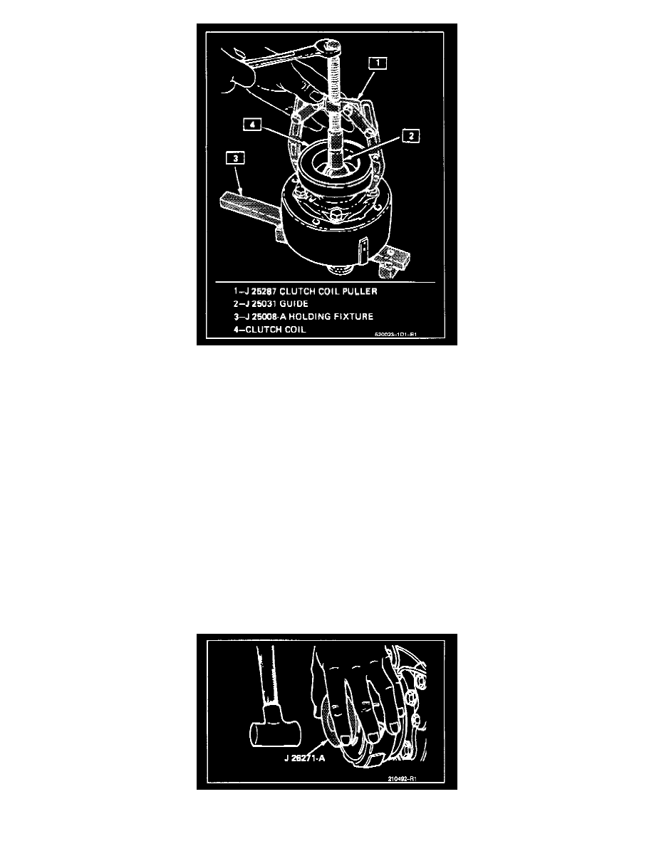
2. Remove the pulley rotor and bearing assembly. Mark the location of the clutch coil terminals on the compressor.
3. Install Rotor and Bearing Puller Guide J 25031 to the front head and install Puller J 8433 with Poly-V-Belt Puller Leg Set J 24092 and remove the
clutch coil from the front head. Clutch coil may also be removed by using rotor and bearing puller guide J 25031 with puller tool J 25287.
Install or Connect
1. Place the clutch coil assembly on the neck of the front head with clutch coil terminals in line with mark described in Step 2 of the removal
procedure.
Installing Rotor And Bearing Assembly (On-Vehicle)