
G 20 Van V6-262 4.3L VIN Z (1993)
VSS Circuit
Circuit Description:
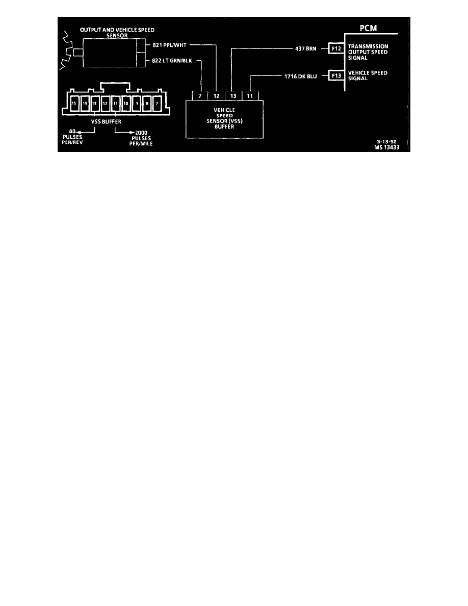
The speed sensor circuit consists of a magnetic induction type sensor, a vehicle speed sensor buffer module and wiring. Gear teeth pressed on the
output shaft induce an alternating current in the sensor. This signal is transmitted to the buffer. The buffer compensates for various axle ratios and
converts the signal into a square wave for use by the speedometer, cruise control, antilock brakes and PCM. The buffer sends two different signals
to the PCM. The 437 circuit relays the transmission output speed which is used to control shift points, line pressure, TCC, DTC 24 and DTC 72.
The 1716 circuit relays the vehicle speed which is used to control engine operating functions and DTC 16.
Test Description: Number(s) below refer to circled number(s) on the diagnostic chart.
1. This test checks the vehicle speed sensor signal to the PCM.
2. This test checks the vehicle speed sensor signal at the buffer module.
3. This test checks the vehicle speed sensor signal directly,
Diagnostic Aids:
Check all connections at the transmission pass-thru connector Refer to PCM Intermittent Diagnostic Trouble Codes or Performance."