
G 20 Van V6-262 4.3L VIN Z (1993)
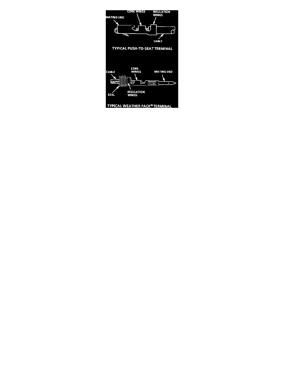
Fig. 22 Terminal Repair
The following repair procedures can be used to repair Push-to-Seat, Pull-to-Seat or Weather Pack(R) terminals, Fig. 22. Some terminals do not require
all steps shown. Skip those that don't apply. (Refer to GM Terminal Repair Kit J 38125-A for further information.)
Step 1:
Cut off terminal between core and insulation crimp (minimize wire loss) and remove seal for Weather Pack(R) terminals.
Step 2:
Apply correct seal per gauge size of wire and slide back along wire to enable insulation removal (Weather Pack(R) terminals only).
Step 3:
Remove insulation.
Step 4:
Align seal with end of cable insulation (Weather Pack(R) terminals only).
Step 5:
Position strip (and seal for Weather Pack(R)) in terminal.
Step 6:
Hand crimp core wings.
Step 7:
Hand crimp insulation wings (non-Weather Pack(R)). Hand crimp insulation wings around seal and cable (Weather Pack(R)).
Step 8:
Solder all hand crimped terminals.
Basic Troubleshooting Guide
TROUBLESHOOTING GUIDELINES
Without a basic knowledge of electricity, it will be difficult to use the diagnostic procedures contained in this section. You should understand the
basic theory of electricity and know the meaning of voltage, current (amps) and resistance (ohms). You should understand what happens in a
circuit with an open or a shorted wire. You should be able to read and understand a wiring diagram. The following four-step troubleshooting
procedure is recommended:
Step 1: Check the problem
Perform a System Check to determine a symptom. Don't waste time fixing part of the problem! Do not begin disassembly or testing until you have
narrowed down the possible causes.
Step 2: Read the electrical schematic
Study the schematic. Read the Circuit Description text if you do not understand how the circuit should work. Check circuits that share wiring with
the problem circuit. (Shared circuits are shown on Power Distribution, Ground Distribution, Fuse Block Details and Light Switch Details pages.)
Try to operate the shared circuits. If the shared circuits work, then the shared wiring is OK. The cause must be within the wiring used only by the
problem circuit. If several circuits fail at the same time, chances are the power (fuse) or ground circuit is faulty.
Step 3: Find the fault and repair
^
Narrow down the possible causes.
^
Use the Troubleshooting Hints.
^
Make the necessary measurements or checks as given in the System Diagnosis.
^
Before replacing a component, check power, signal and ground wires at the component harness connector. If the checks and connections are
OK, the most probable cause is component failure.
Step 4: Test the repair