
G 20 Van V6-262 4.3L VIN Z (1993)
Throttle Position Sensor: Description and Operation
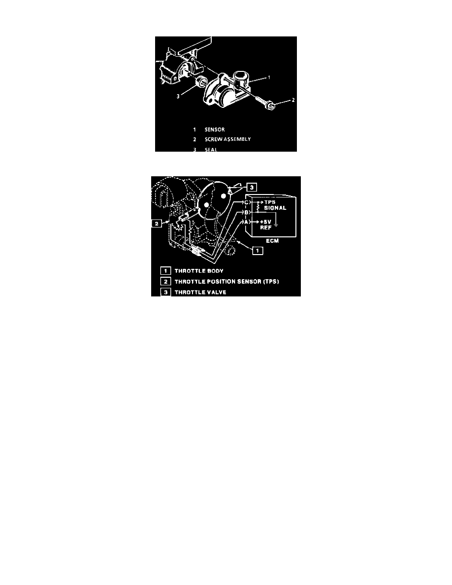
Throttle Position (TP) Sensor
Throttle Position Sensor (TPS)
PURPOSE
The Throttle Position (TP) Sensor is a non-adjustable potentiometer that senses throttle angle and relays the information to the control module.
This input to the control module is used to control the fuel system and most of the control module outputs.
CONSTRUCTION
The Throttle Position (TP) sensor is mechanically connected to the throttle shaft on gasoline applications or the injector pump on diesel
applications. It is a potentiometer with one end connected to 5 volts from the PCM and a second wire to ground. A third wire is used by the PCM
to measure voltage across the TP sensor.
OPERATION
As the throttle valve rotates in response to movement of the accelerator pedal, the throttle shaft transfers this rotation movement to the TP sensor.
A potentiometer (variable resistor) within the Throttle Position (TP) sensor assembly changes its resistance in proportion to throttle movement.
If the TP sensor senses a Wide Open Throttle proportion to throttle movement. (WOT), a voltage signal indicating this condition is sent to the
control module. The control module then increases the injector base pulse width, permitting increased fuel flow.
By applying a reference voltage (5.0 volts) to the TP signal input, a varying voltage (reflecting throttle position) is available at the TP output. For
example, approximately 2.5 volts results from a 50% throttle valve opening (depending on TP calibration). The voltage output from the TP
assembly is routed to the control module for use in determining throttle position.
SCAN TOOL INFORMATION
A scan tool can display throttle position in volts and should range from below 1.25 volts at closed throttle to over 4.0 volts at Wide Open Throttle
(WOT).
A scan tool can also display throttle position in throttle angle. This angle is displayed in percent and should range from 0% at closed throttle, to
100% at Wide Open Throttle (WOT).
If a fault does occur in the TP circuit DTC 21 or DTC 22 will set. In addition, the TCC will be disabled, fourth gear will be inhibited, and the
PCM will cause the pressure control solenoid to set line pressure high causing harsh shifts.
LOCATION
The non-adjustable Throttle Position (TP) sensor, is mounted on the side of the throttle body opposite the throttle lever assembly.