
G 20 Van V6-262 4.3L VIN Z (1993)
Control Valve Body (Key)
Fig. 5
Install or Connect
1. Valve body assembly (350 in Fig. 4).
^
Connect the manual valve link (89 in Fig. 3) to the inside detent lever (88 in Fig. 4).
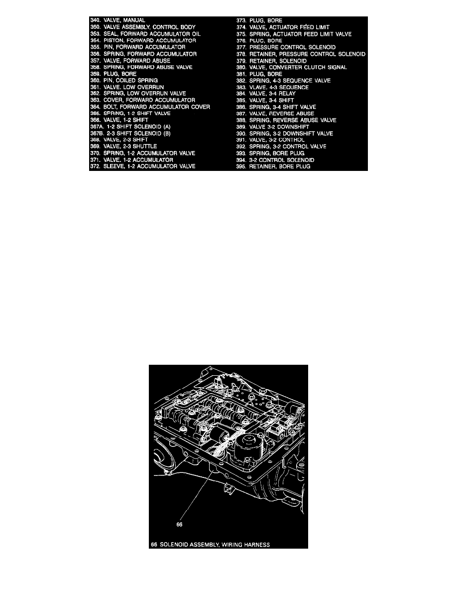
2. Wiring harness (66 in Fig. 2), manual spring assembly (63 in Fig. 2), pressure switch assembly (69 in Fig. 2) and all remaining valve body
bolts.
Note: Torque valve body bolts in a spiral pattern starting from the center. If bolts are torqued at random, valve bores may be distorted and inhibit
valve operation.
3. Pressure switch assembly bolt (70 in Fig. 2) and pressure switch assembly (69 in Fig. 2).
Tighten
^
Bolts (68) to 11 N.m (8 ft. lbs.)
Solenoids And Wiring Harness