
G 20 Van V8-350 5.7L VIN K TBI (1995)
Throttle Body: Description and Operation
With TBI Model 295
TBI 295 Unit Operation
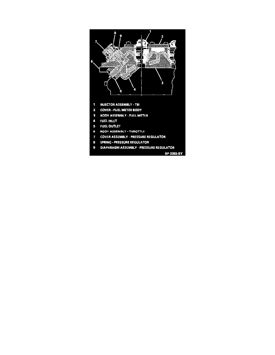
Throttle Body Injection (TBI) Unit 295 consists of three assemblies:
Fuel meter cover with:
-
Fuel pressure regulator.
Fuel meter body with:
-
Fuel injectors.
Throttle body with:
-
Idle air control valve.
-
Throttle position sensor.
VACUUM PORTS
The throttle body portion of the TBI unit may contain ports located above, or below the throttle valve. These ports generate the vacuum signals for
the Exhaust Gas Recirculation (EGR) valve, MAP sensor, and the EVAP canister purge system.
FUEL INJECTORS
The fuel injectors are solenoid activated, controlled by the PCM. The PCM turns on the solenoids, which lifts a normally closed ball off a seat.
Fuel, under pressure, is injected in a conical spray pattern at the walls of the throttle body bore above the throttle valve.
The fuel that is not used by the injectors passes through the pressure regulator before being returned to the fuel tank.
FUEL PRESSURE REGULATOR
The pressure regulator is part of the fuel meter assembly, and contains an air chamber and a fuel chamber that are separated by a
diaphragm-operated relief valve and a calibrated spring. The regulator's function is to maintain a constant fuel pressure drop across the injector at
all times. Fuel pressure is regulated by the difference between fuel pump pressure acting on one side of the diaphragm and the force of the
calibrated spring (and air cleaner air pressure) acting on the other side. The system operates in an acceptable pressure range of 62 to 90 kPa (9 to
t3 psi).
If the fuel pressure is too low, poor performance could result. If the pressure is too high, excess emissions and unpleasant exhaust odor may result.
IDLE AIR CONTROL (IAC) SYSTEM
Engine idle speeds are controlled by the control module through the Idle Air Control (IAC) valve mounted on the throttle body. The control
module sends voltage pulses to the IAC motor windings causing the IAC motor shaft and pintle to move "IN" or "OUT" a given distance (number
of steps) for each pulse (called counts).
This movement controls airflow around the throttle plate, which in turn, controls engine idle speed, either cold or hot. IAC valve pintle position
counts can be seen using a Tech 1 scan tool. Zero (0) counts correspond to a fully closed passage, while 140 counts or more (depending on the