
G 20 Van V8-350 5.7L VIN K TBI (1995)
Ignition Switch Lock Cylinder: Service and Repair
Important:
This new procedure involves drilling a hole through the plastic ignition switch and into the lock cylinder slightly to break or access a cylinder
release button retaining spring (similar to G, J and N models). The removal of the broken spring and then the release button will allow the switch
to be reused.
1.
Remove the necessary trim panels to gain access to the instrument panel mounted switch (refer to information in "Body and Accessories Section,
Instrument Panel, Gauges and Consoles").
a.
On instrument panel mounted N models (Malibu and Cutlass), the switch and cylinder can be accessed after removing the instrument cluster
assembly and positioning the switch/cylinder upward in the cavity for the cluster assembly.
b.
On Corvette models, the switch and cylinder can be accessed after removing the knee bolster from the lower instrument panel area and
positioning the switch/cylinder downward from its location on the instrument panel.
2.
Loosen switch from instrument panel and disconnect the electrical connections, BUT NOT the cable connection for BTSI (Brake/Transmission
Shift Interlock).
3.
Protect the immediate work area with a fender cover or other suitable material.
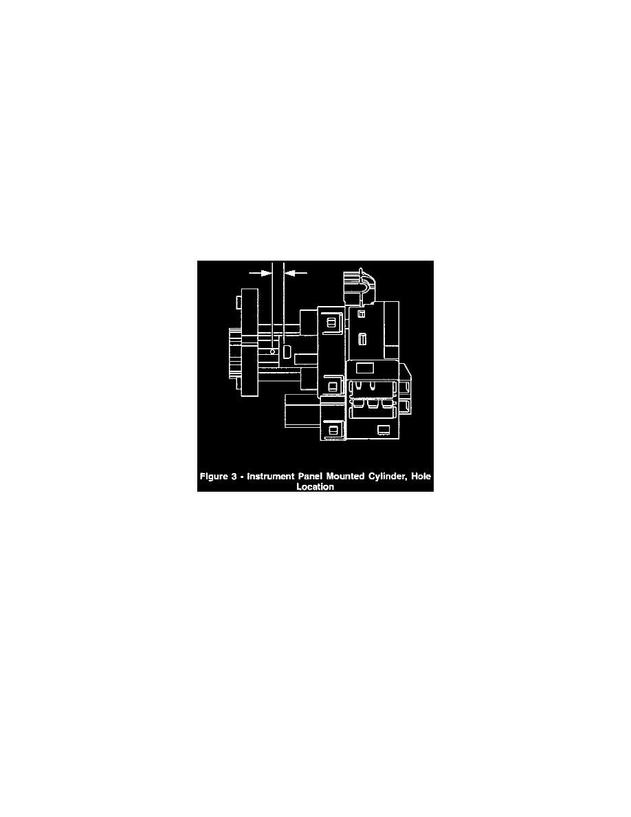
4.
Locate the surface for the cylinder release button on the plastic ignition switch housing and center punch a location on the "rib" approximately
3/8" rearward (toward the key entry end) from the cylinder release button, see Figure 3.
5.
Using a 1/8" drill bit, carefully drill a pilot hole through the plastic housing only.
6.
Using a 9/32" drill bit, carefully drill a larger hole at the pilot location, and slightly into the lock cylinder surface to break the release button
retaining spring.
7.
Remove portions of the broken spring from the hole using a small pair of needle nose pliers (or other suitable tool) and turn switch over to shake
out the release button.
8.
Grasp the lock cylinder, remove it from the switch housing.
9.
Remove any plastic "flash" from the drilling operations and, using compressed air, blow out the ignition switch assembly.
10.
Follow the procedures in the General Information Section of the appropriate vehicle Service Manual when recoding of cylinders is required.
11.
Install the new cylinder(s) as required by rotating both the cylinder and ignition switch to the "ON" position and pushing the cylinder into the
switch. It may be necessary to depress the release button slightly as it passes by the 9/32" hole previously drilled in the housing.
12.
Reassemble the ignition switch and instrument panel components as indicated by the appropriate Service Manual.