
G 20 Van V8-379 6.2L DSL VIN C FI (1992)
2.
Disconnect the TP sensor connector and insert jumper wires between the sensor and harness. Jumpers can be made using the following terminal
P/N information. Refer to the "Throttle Position Sensor Data" chart. Three jumper wires or their equivalent will be necessary (figure 1).
3.
Turn key to "ON" (engine not running).
4.
Using a digital multimeter J 39200 or equivalent, measure the voltage from the TP sensor connector terminals "A" to "C." This is the voltage
reference.
IMPORTANT:
* The TP sensor voltage is displayed by the TECH 1, however, it's recommended that only the multimeter be used to set the TP sensor as the
TECH 1 voltage may read higher than the multimeter.
5.
Multiply the voltage ratio x voltage reference number (from step 4) = required TP sensor voltage setting.
Example: 0.33 (voltage ratio x 4.97 (voltage reference) = 1.64 volts (desired voltage setting). Refer to the *Throttle Position Sensor Data" chart
for calculating the correct TP sensor voltage setting.
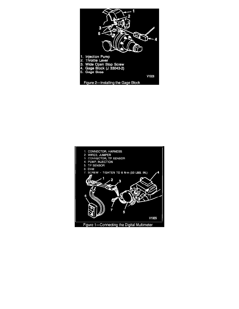
6.
Insert the 0.646 side of the TP sensor gauge block (J 33043-2) between the gauge boss on the injector pump and the wide-open stop screw on the
throttle lever (figure 2).
7.
Rotate the throttle lever toward the wide-open position so that the gage block is held firmly in place.
8.
Measure the voltage between terminals "B" and "C." This is the TP sensor voltage. It must be within the following specified tolerance of the
desired TP sensor voltage setting. Refer to the "Throttle Position Sensor Data" chart.
Example: The actual TP sensor voltage for TP sensor (GM P/N 101 37417) should be between 1.62 volts and 1.66 volts. For engines equipped
with (GM P/N 14071076) TP sensor voltage is between 3.10 and 3.16 volts.
9.
If the TP sensor voltage is within tolerance, then proceed to step 12.
10.
To adjust the TP sensor, loosen the two attaching screws and rotate the TP sensor to its full left position (facing sensor). Rotate the sensor back to
the right until the desired sensor voltage setting (from step 5) is obtained. (Note: To obtain the correct position, the sensor must be rotated to the
right from its full left position.)
11.
When the correct voltage is obtained, hold the sensor in this position and tighten the attaching screws to 6 N-m (53 lbs.in.).
12.
Release the throttle lever and allow it to return to the idle position. Open the throttle lever back against the gauge block and re-check the TP
sensor. It must be within the specified tolerance of the required TP sensor voltage. Refer to the "Throttle Position Sensor Data" chart. Return to