
G 20 Van V8-393 6.5L DSL VIN Y (1995)
Clockspring Assembly / Spiral Cable: Service and Repair
Prior to performing replacement procedures, disarm air bag system. Refer to, Service and Repair/ Air Bag System Disarming & Air Bag
System Arming. Refer to, / Specifications/ Mechanical for torque values when installing components.
All sensors and mounting bracket bolts must be carefully torqued to assure proper operation. Never power up the air bag system when any
sensor is not rigidly attached to the vehicle, since the sensor could be activated when not attached, causing air bag deployment.
SIR coil assembly will become uncentered if steering column is separated from steering gear and is allowed to rotate or centering spring is
pushed down, letting hub rotate while coil assembly is removed from steering column.
1. Disconnect battery ground cable, then remove steering wheel as follows:
a. Remove inflator module.
b. Remove steering wheel nut, then disconnect horn lead assembly.
c. Mark relationship of steering wheel to steering shaft, then remove steering wheel using steering wheel puller tool No. J-1859-03, or equivalent.
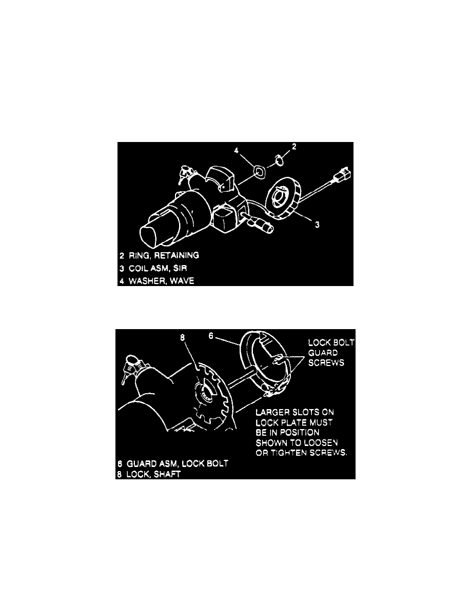
Fig. 10 SIR Coil Assembly Removal
2. Remove coil assembly retaining ring, then the wave washer, Fig. 10.
Fig. 11 Lock Bolt Guard Removal
3. With tilt steering, proceed as follows:
a. Place ignition switch in Run position, then rotate steering shaft assembly until block tooth is at 7 o'clock position and bolt guard screws are
accessible through wide slots in shaft lock, Fig. 11.
b. Loosen screws on lock bolt guard until guard can be removed. Screws will be attached to lock bolt guard.
c. Place ignition switch in Lock position.
4. Remove shaft lock retaining ring using lock plate compressor tool No. J-23653-SIR, or equivalent, to push down shaft lock. Discard ring.
5. Remove shaft lock, then the turn signal cancel cam.
6. Remove upper bearing spring, inner race seat and inner race.
7. Position turn signal lever in right turn (up) position, then remove multi-function switch as described under appropriate chassis chapter.