
G 2500 3/4 Ton Van V8-305 5.0L VIN M SFI (1997)
Fuel Supply Line: Service and Repair
Fuel Hose and Pipes
Fuel Feed And Return Pipes Fittings
Diagram
Diagram
REMOVAL PROCEDURE
1. Disconnect the negative battery cable.
2. Relieve the fuel system pressure. Refer to the Fuel Pressure Release Procedure.
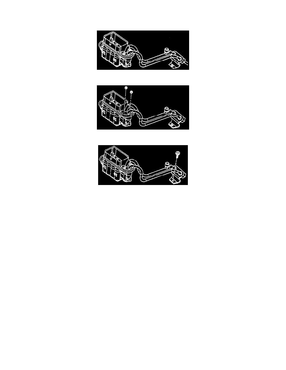
3. Disconnect the fuel lines at rear of the intake manifold.
4. Remove the nuts
5. Remove the retainer
6. Disconnect the injector fuel inlet pipe and the outlet pipe.
7. Remove the rear fuel line bracket.
8. Pull straight up on fuel pipe to remove fuel pipes from injector assembly.
IMPORTANT: Check the injector assembly to insure the O-rings have been removed, using the seal retainer tool.
9. Remove the O-ring seals from both ends of the fuel feed and return pipes and discard.
Assemble Procedure
Install the new O-rings into the inlet and outlet of the fuel injector assembly, using the seal retainer tool.
INSTALLATION PROCEDURE
CAUTION: To Reduce the Risk of Fire and Personal Injury:
Before connecting the fitting, always apply a few drops of clean engine oil to the male pipe end. This will ensure proper reconnection and
prevent a possible fuel leak. (During normal operation, the O-rings located in the female connector will swell and may prevent proper
reconnection if not lubricated.
IMPORTANT: Remember to install the new O-rings into the inlet and outlet of the fuel injector assembly, using the seal retainer tool.
1. Apply a few drops of clean engine oil to the male tube ends.
2. Connect the fuel feed and return pipes to fuel assembly.