
G 30 1 Ton Van L6-250 4.1L VIN D 2-bbl (1983)
Diode: Technical Service Bulletins
Isolation Diodes - Replacement Information
Number: 93-163-8A
Section: 8A
Date: MAY 1993
Corporate Bulletin No.: 178201R
ASE No.: A6
Subject:
ISOLATION DIODES REPLACEMENT INFORMATION
Model and Year:
1993 AND PRIOR YEAR PASSENGER CARS AND TRUCKS
THIS BULLETIN CANCELS AND SUPERSEDES DEALER SERVICE BULLETIN NO. 92-47-8A, DATED NOV. 1991. THE 1993 MODEL YEAR
HAS BEEN ADDED AS WELL AS PART NUMBERS HAVE BEEN REVISED. THIS WILL ALSO UPDATE CERTAIN SERVICE MANUALS.
ALL COPIES OF 92-47-8A SHOULD BE DISCARDED.
Many of the electrical systems on our vehicles use a diode to isolate certain circuits and protect them from voltage spikes. Some of the circuits which
may use such a diode are listed below:
A/C Compressor Clutch
ABS/4WAL
NOTE:
The ABS diode on the Delco Moraine system is hidden inside of an electrical connector under the carpet at the right kick panel.
Wiper
Charging System (hidden in wire harness)
Parking Brake (vehicles with ABS)
Relays
Solenoids
Diesel Glow Plug Circuit
Day Time Running Lights
Obtaining replacement diodes can sometimes be a problem. A universal diode, that meets the specifications in the chart below, may be used for the
applications listed above. Since certain diode applications have specific part numbers, always reference the applicable GM parts catalogue before
installing one of the universal diodes listed in this bulletin.
When installing the new diode, use the following procedures to obtain a lasting repair:
1.
If the diode is taped to the harness, remove all of the tape.
2.
Paying attention to current flow direction, remove inoperative diode from the harness with a suitable soldering tool. If the diode is located next to a
connector terminal, remove the terminal(s) from the connector to prevent damage from the soldering tool.
3.
Carefully strip away a section of insulation next to the old soldered portion of the wire(s). Do not remove any more than is needed to attach the
new diode.
4.
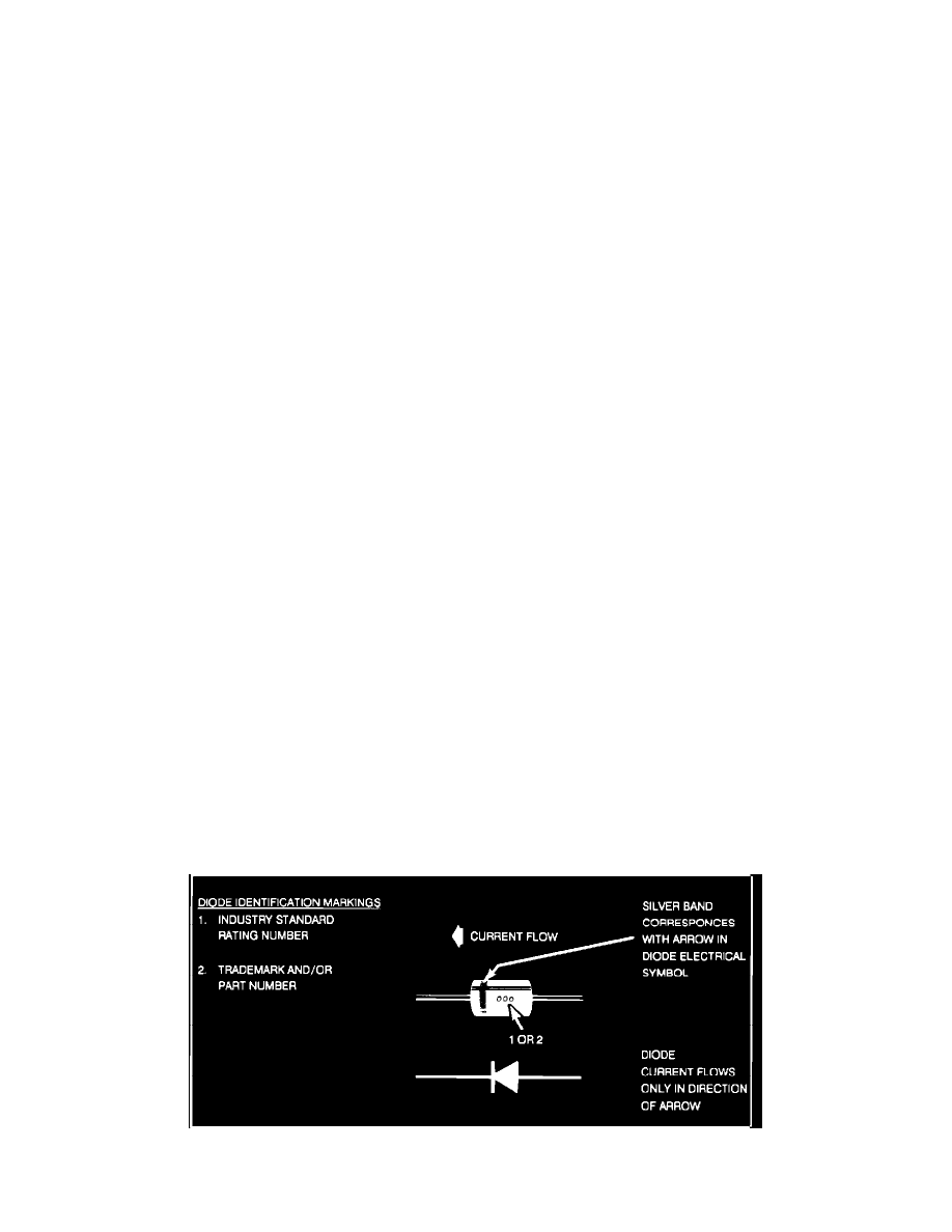
Check current flow direction of the new diode, being sure to install the diode with correct bias. Reference the appropriate service manual wiring
schematic to obtain the correct diode installation position. Reference Figure 1 for replacement diode symbols and current flow explanations.