
G 30 Van V8-454 7.4L VIN N TBI (1995)
Bearing Staked In Place
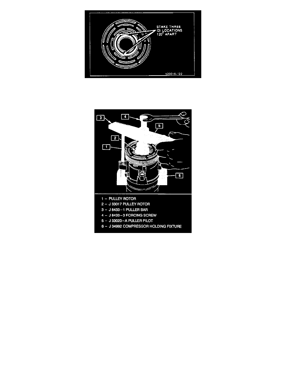
The stake metal should not contact the outer face of the bearing to prevent the possibility of distorting the outer race. Stake three (3) places 120°
apart as shown in the illustration.
Installing Pulley Rotor And Bearing Assembly
5. With the compressor mounted to the J 34992 holding fixture, position the rotor and bearing assembly on the front head.
6. Position the J 33017 pulley rotor and bearing installer and J 33023-A puller pilot directly over the inner race of the bearing.
7. Position puller crossbar J 8433-1 on the puller pilot J 33023-A and assemble the two J 34992-2 through bolts and washers through the puller bar
slots and thread them into the J 34992 holding fixture. The thread of the through bolts should engage the full thickness of the holding fixture.
8. Tighten the center screw in the J 8433-1 puller crossbar to force the pulley rotor and bearing assembly onto the compressor front head. Should the
J 33017 pulley rotor and bearing installer slip off direct in-line contact with the inner face of the bearing, loosen the J 8433-3 center forcing screw
and realign the installer and pilot so that the J 33017 installer will properly clear the front head.
9. Install rotor and bearing assembly retainer ring, using snap ring pliers J 6083.
10. Reinstall clutch plate and hub assembly as described previously.
Clutch Coil
Remove or Disconnect
1. Perform Steps J through 4 of "Clutch Rotor and/or Bearings" removal procedure. Mark clutch coil terminal location on compressor front head.