
G 30 Van V8-454 7.4L VIN N TBI (1995)
On-Vehicle
Install or Connect
1. Dip the new seal O-ring in clean 525 viscosity refrigerant oil and assemble onto O-Ring Installer J 33011.
2. Insert the O-Ring Installer J 33011 completely down into the compressor neck until the Installer "bottoms". Lower the moveable slide of the
O-Ring Installer to release the O-Ring into the seal seat O-ring lower groove. (The compressor neck top groove is for the shaft seal retainer ring.)
Rotate the Installer to seat the O-ring and remove the Installer.
3. Prepare Lip Seal:
^
Dip the new Lip Seal in clean 525 viscosity Refrigerant Oil and assemble Lip Seal to Seal Installer, J 23128-A. The printed/stamped steel case
side of Lip Seal must he engaged with knurled tangs of installer so that flared-out side of Lip Seal is facing and installed towards the
compressor.
4. Install Lip Seal:
^
Place Seal Protector J 34614 over end of compressor shaft and slide new seal onto the shaft with a rotary motion until it stops. Take care not to
dislodge the O-Ring. Disengage installer from seal and remove seal protector from compressor shaft.
NOTICE: Handling and care of seal protector is important. If seal protector is nicked or the bottom flared, the new seal may be damaged during
installation.
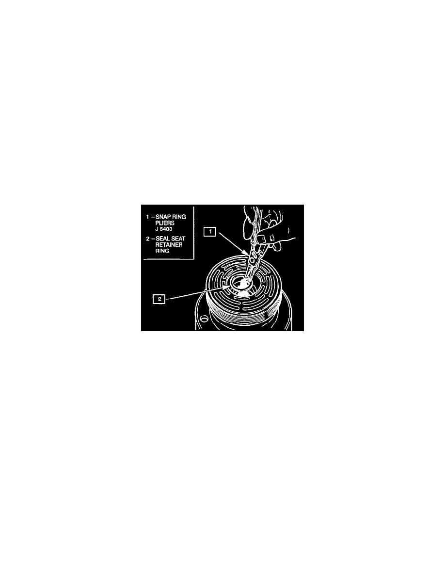
Removing And Installing Shaft Seal Seat Retaining Ring
5. Install the new seal seat retainer ring with its flat side against the Seal Seat, using Snap-Ring Pliers J 5403. Use the sleeve from O-Ring installer J
33011 to press in on the seal seat retainer ring so that it snaps into its groove.
6. To leak test, install compressor leak test fixture J 39893 on rear head of compressor and connect gage charging lines and J 39500-GM Refrigerant
Recovery System. Pressurize suction and high-side of compressor with R-134a Refrigerant. Temporarily install (M9 x 1.25 thread on shaft) nut
and. with the compressor in horizontal position, rotate the compressor shaft in normal direction of rotation several turns by hand. Leak test the seal
area and correct any leak found. Recover the refrigerant. Remove shaft nut.
7. Remove any excess oil, resulting from installing the new seal parts, from the shaft and inside the compressor neck.
8. Install the Clutch Plate and Hub assembly as described in minor repair procedures.
9. Reinstall compressor belt and tighten bracketry.
10. Evacuate and Charge the Refrigerant System using J 39500-GM.
11. Leak Test Refrigerant System using J 39400 Leak Detector.
Off-Vehicle
Install or Connect
1. Follow applicable on-vehicle procedures.